# ID: 6111
## Title: The September Sweet Spot: Do This In August To Beat The October Commercial HVAC Maintenance Rush
## Type: blog_post
## Author: Ben Reed
## Publish Date: 2025-08-07T14:34:35
## Word Count: 1088
## Categories: HVAC Maintenance, Commercial Systems, Heating Systems
## Tags: carbon monoxide safety, fall heating maintenance, furnace inspection, heat exchanger inspection, HVAC business planning, HVAC maintenance, HVAC revenue optimization, maintenance agreements, preventive maintenance, seasonal HVAC planning, September scheduling, small business HVAC, technician burnout, technician training, winter emergency prevention, work-life balance
## Permalink: https://hvacknowitall.com/blog/the-september-sweet-spot-commercial-hvac-maintenance
## Description:
Key Takaways
- September maintenance prevents common winter HVAC failures including circulation pump seizures, heat exchanger cracks, and ignition problems that typically manifest in December/January
- Scheduling maintenance in September offers technical advantages (equipment accessibility, thorough inspections) and business benefits (increased profit margins, efficient routing)
- Customers avoid the October/November maintenance bottleneck when wait times stretch to 2 weeks and parts availability becomes limited
- Implementing September maintenance programs reduces technician burnout by spreading workload evenly throughout the year, reducing 60+ hour winter weeks
```
Working in residential HVAC? Read this complimentary article!
```
## The October Problem: Why Waiting Costs Everyone
Once the first cold snap hits in October, the phone starts ringing with heating emergency calls. Suddenly, everyone needs their heating systems operational *yesterday*. This creates a cascade of familiar challenges:
- Building managers discover major heat exchanger issues when they need heat most
- Parts availability plummets as suppliers can’t keep up with the surge in demand
- Emergency service rates kick in, costing clients 50-100% more than scheduled maintenance
- Technician workloads become unmanageable, creating a work-life imbalance during the heating transition
When these problems are discovered late, the consequences create legitimate safety hazards.
## The September Sweet Spot: Why It’s Ideal Timing
September offers unique advantages that make it the perfect time for commercial heating maintenance:
- Moderate weather allows system shutdowns without disrupting building occupants
- Technicians are transitioning from peak AC season to a more balanced workload
- Parts suppliers still have healthy inventory before the October/November depletion
- Building managers typically have fiscal year budget available for necessary repairs
This timing sweet spot creates a win-win situation for both service providers and clients. Technicians can work more methodically without emergency pressure, while building managers avoid the premium costs and disruption of mid-winter failures.
## The Business Case for September Maintenance in Commercial Buildings
Well-planned maintenance is essential for commercial buildings to keep critical infrastructure running smoothly and generating ROI for all stakeholders:
- Preventive maintenance delivers a 545% return on investment compared to reactive emergency repairs
- Buildings with proper heating maintenance experience 40-60% fewer winter heating failures
- Emergency repairs during peak heating season cost 50-100% more than scheduled maintenance
- Well-maintained commercial heating equipment lasts 14+ years versus just 9 years for neglected systems
As an HVAC tech, if you’re aware of the impacts to a business and can present this data effectively, you can position yourself as business partners rather than just service providers.
## Critical Commercial Systems That Can’t Wait
### Rooftop Units (RTUs)
RTUs demand specialized attention before heating season begins. This includes:
- Heat exchanger inspection using proper techniques to identify hairline cracks and corrosion
- Thorough burner inspection and cleaning to prevent carbon monoxide issues
- Control system recalibration to ensure proper heating sequences and prevent short cycling
Our detailed guide on [Gas Manifold Pressure Testing](https://www.hvacknowitall.com/blogs/blog/231593-hvac-tip----checking-manifold-gas-pressure) provides step-by-step procedures for ensuring your gas-fired RTUs operate safely and efficiently. This critical test often reveals issues that can be addressed easily in September but become emergency calls by November.
### Boiler Systems
Commercial boilers benefit tremendously from September attention:
- Comprehensive combustion analysis to optimize efficiency before the heating season demands
- Safety control verification to identify potential failure points before they become critical
- Water treatment analysis to prevent mid-winter scale buildup and efficiency losses
As covered in our [Seasonal Changeover Guide](https://hvacknowitall.com/blog/changeover-from-cooling-to-heating), proper glycol concentration verification is essential for hydronic systems to ensure freeze protection during the coming winter months. This simple step performed in September prevents catastrophic pipe failures when temperatures plummet.
### Building Automation Systems
[The brain of your commercial building](https://hvacknowitall.com/blog/bms-basics-hvac-technician-guide) requires specialized attention:
- Schedule updates to optimize heating mode operation and prevent energy waste
- Sensor calibration verification to ensure accurate temperature readings and prevent comfort complaints
- Control sequence testing to identify programming issues before occupants require consistent heating
## Immediate Action Plan: What to Do In Early August
1. **Create a targeted outreach strategy**: Develop a list of commercial clients prioritizing those with critical operations or aging equipment.
2. **Develop a streamlined inspection checklist**: Create a September-specific checklist that focuses on heating components most likely to fail during the first cold snap.
3. **Implement a prioritization system**: Schedule the most critical systems first—hospitals, elder care facilities, schools, and buildings with previous heating issues.
4. **Set up a parts inventory plan**: Coordinate with suppliers to ensure availability of commonly needed heating components.
When discussing flame rectification systems, reference our guide on [Why Flame Rod Failures Happen and How To Prevent Them](https://hvacknowitall.com/blog/why-flame-rod-failures-happen-and-how-to-prevent-them), which provides technical insights that can help you identify potential issues before they cause no-heat conditions.
## Long-Term Strategy: Building a September Maintenance Program
To truly differentiate your commercial service, develop a systematic September maintenance program:
- Create an annual reminder system to book commercial clients specifically for September heating checks
- Develop educational materials explaining the September advantage for building managers
- Implement technician training focused on efficient heating system inspections
- Build performance tracking that documents reduced winter emergency calls after September maintenance
For comprehensive maintenance of specialized systems, our guide on [Make Up Air Units](https://hvacknowitall.com/blog/make-up-air-units-explained) provides detailed procedures for both direct-fired and indirect-fired systems, which are often overlooked during standard maintenance but critical to proper building operation.
## Communication Strategies for Building Managers
The success of September maintenance often relies on effective communication with building managers:
- Frame conversations around budget protection rather than maintenance costs
- Address the “it’s still hot outside” objection with data on equipment lead times
- Present tenant satisfaction benefits of avoiding mid-winter heating emergencies
- Provide documentation that helps justify maintenance expenditures to upper management
These conversations build trust and position you as a proactive partner rather than a reactive vendor.
## The September Advantage
Implementing September heating maintenance sets commercial HVAC technicians apart as true professionals in an industry often driven by reactive service. This approach delivers multiple benefits:
- Peace of mind from addressing issues before they become emergencies
- Balanced workload that prevents the October/November service chaos
- Higher client satisfaction and stronger long-term relationships
- Increased revenue through more efficient service delivery
By embracing the September advantage, you position yourself as a strategic asset to your clients rather than just another service provider.
```
Important Note: As our guide on Carbon Monoxide Testing emphasizes, safety must remain the top priority in all heating maintenance. September inspections provide the time needed to thoroughly evaluate combustion safety without the pressure of freezing occupants or emergency conditions.
```
--------------------------------------------------
# ID: 6104
## Title: The September Sweet Spot: Why Smart Residential Techs Schedule HVAC Maintenance In August
## Type: blog_post
## Author: Ben Reed
## Publish Date: 2025-08-07T13:28:12
## Word Count: 1541
## Categories: HVAC Maintenance, Heating Systems
## Tags: carbon monoxide safety, fall heating maintenance, furnace inspection, heat exchanger inspection, HVAC business planning, HVAC maintenance, HVAC revenue optimization, maintenance agreements, preventive maintenance, seasonal HVAC planning, September scheduling, small business HVAC, technician burnout, technician training, winter emergency prevention, work-life balance
## Permalink: https://hvacknowitall.com/blog/the-september-sweet-residential-spot-hvac-maintenance
## Description:
Key Takeaways
- September maintenance prevents common winter HVAC failures including circulation pump seizures, heat exchanger cracks, and ignition problems that typically manifest in December/January
- Scheduling maintenance in September offers technical advantages (equipment accessibility, thorough inspections) and business benefits (increased profit margins, efficient routing)
- Customers avoid the October/November maintenance bottleneck when wait times stretch to 2 weeks and parts availability becomes limited
- Implementing September maintenance programs reduces technician burnout by spreading workload evenly throughout the year, reducing 60+ hour winter weeks
```
Working in commercial HVAC? Read this complimentary article!
```
## Why Timing Matters for Shoulder Season Maintenance
Are you ready for the October maintenance rush. Probably not.
Data shows October and November rank as the busiest maintenance months for HVAC contractors, creating a bottleneck that leaves customers waiting up to two weeks for service.
By the time most customers think about heating maintenance, it’s already too late. They call when the first cold snap hits, and suddenly everyone wants their furnace checked at once. This creates a scheduling nightmare that forces you to rush through jobs, miss important safety checks, and work overtime that could have been avoided.
[Changing over from cooling to heating](https://hvacknowitall.com/blog/changeover-from-cooling-to-heating) is a process that requires careful inspection and preparation. When systems sit dormant for months, problems develop that only manifest when they’re first fired up – usually on the coldest day of the year.
## What’s Breaking Down This Winter (And Why)
After sitting dormant all summer, heating systems develop predictable failure points that smart technicians check before problems occur. Here are the top components to inspect during September maintenance:
1. **Circulation Pumps**: These top the failure list after summer inactivity. Pump seizure due to 3-4 months of dormancy is a primary breakdown cause. A simple manual rotation during September can prevent an expensive mid-winter replacement.
2. **Induced Draft Motors**: These critical components often seize after months of inactivity due to moisture infiltration and bearing lubricant thickening. The bearings in these motors are particularly vulnerable to corrosion when the system isn’t running regularly. A preventative check includes testing for smooth operation, proper amperage draw, and inspecting wheel clearance before winter demand pushes these motors to failure.
3. **Ignition Systems**: Ignitors frequently fail due to exhaust gas recirculation during startup. Testing spark location and conductivity now prevents no-heat calls later.
4. **Burners**: Summer humidity causes rust and corrosion on burner surfaces, leading to improper flame patterns and inefficient combustion when winter arrives. Carefully inspect burners for warping, rust, and proper alignment, then clean thoroughly with appropriate brushes and compressed air. Many techs skip this step, but it’s essential for preventing carbon monoxide issues and ignition failures.
5. **Flame Sensors**: These develop contamination buildup during the off-season that leads to system failures. A quick cleaning in September ensures reliable ignition when temperatures drop.
6. **Heat Exchangers**: Heat exchanger inspection deserves special attention during September maintenance. Even small cracks can release deadly carbon monoxide into living spaces when systems activate for winter. CO is known as the [silent killer](https://hvacknowitall.com/blog/carbon-monoxide-the-silent-killer-every-tech-should-know-how-to-handle) because it’s odorless, colorless, and dangerous at just 70 ppm, with 400 ppm potentially causing death within hours. Professional-grade testing equipment allows technicians to check ambient air, mechanical rooms, and flue gas during maintenance visits – any reading above 200 ppm in flue gas or detection in the air stream indicates an immediate safety hazard requiring system shutdown.
7. **Condensate Drains**: One of winter’s most overlooked failure points is condensate drainage systems in high-efficiency furnaces. After months without operation, organic growth, debris accumulation, and trap evaporation create perfect conditions for water backups that trigger pressure switches and shut systems down. Many emergency “no heat” calls are simply condensate issues that could have been prevented with September maintenance. Thoroughly flush these lines, verify proper trap depth, and consider adding condensate treatment tablets as preventative maintenance
8. **Control Boards**: The “brain” of modern furnaces often fails after power surges during summer thunderstorms. Testing all functions during the mild weather allows for planned replacement rather than emergency service. [Learn more about control board components here.](https://hvacknowitall.com/blog/guide-to-hvac-pcb-components)
January experiences the highest breakdown rate at 15% of annual heating system failures, followed by December at 12%. [By addressing these components during September’s maintenance sweet spot](https://hvacknowitall.com/blog/the-truth-about-furnace-tune-ups), you’re preventing the most common emergency calls while protecting your customers’ comfort and safety.
## Immediate Actions in August
The time to act is now, not when the rush hits. Here are the concrete steps you can take in early august to leverage the September sweet spot:
### Customer Communication Templates
Start with your existing customer base. Send a simple email with this message:
> *“Beat the October rush! Schedule your heating system maintenance in September and receive priority scheduling, our thorough 21-point safety inspection, and peace of mind before the cold weather hits. Plus, mention this email for $25 off when you book this week.”*
For text messages, keep it even simpler:
> *“HVAC Alert: Book your heating maintenance in September to avoid the October rush and potential parts delays. Reply YES for priority scheduling.”*
These templates have produced open rates of 20% for email and 98% for text messages, significantly outperforming industry averages.
### How to Pitch September Maintenance During AC Calls
Every summer service call is an opportunity to book fall maintenance. Here’s a script that works:
> *“While I’ve got your AC running great today, I noticed your heating system hasn’t been checked since last year. Most of our customers book their heating maintenance in September to avoid the October rush when everyone calls at once. Would you prefer a morning or afternoon appointment in the second week of September?”*
This approach uses the psychology of choice rather than yes/no questions, increasing booking rates by up to 35%. By presenting it as something “most customers do,” you’re establishing a social norm that makes the decision easier.
## The Business Case for September
As a solo technician or small shop owner, September maintenance offers a direct path to more stable income and better work-life balance. While emergency calls might seem more profitable at $950 versus $250 for maintenance, consider the hidden value: maintenance calls take half the time, create repeat customers, and can be scheduled on your terms. This means you can complete 6-8 maintenance visits daily compared to 3-4 emergency calls, with less stress and more predictable hours.
For small operations, simple maintenance agreements don’t need fancy software or complicated contracts. Start with a basic one-page agreement offering two seasonal checks (fall and spring), priority emergency service, and a 10% discount on repairs. Price it reasonably at $199-299 annually, and begin by offering it to your most satisfied customers. Even securing just 25 maintenance agreements creates a reliable $5,000-7,500 revenue base that helps smooth seasonal income fluctuations.
The beauty of September maintenance for small shops is that it transforms your business model from “waiting for the phone to ring” to proactively scheduling your workload. While we recommend you use a proper fleet management solution (like Housecall Pro), you can use a simple spreadsheet to track customer equipment age and maintenance history, then group appointments by neighborhood to maximize efficiency.
Many successful one-person operations report that maintenance agreements eventually represent 30-40% of their total revenue while requiring only 20% of their labor hours – making them the most profitable aspect of their business.
## Building Long-Term Strategy
September’s calmer pace creates the perfect opportunity for training newer technicians before emergency season hits. Pairing experienced professionals with apprentices during maintenance calls allows for hands-on learning without the pressure of emergency situations. Companies report technicians trained through structured September maintenance programs experience 40% lower error rates during their first heating emergency season, building the reliability and discretionary effort that distinguish successful HVAC professionals.
Perhaps most importantly, strategic September scheduling dramatically improves technician quality of life by spreading workload more evenly throughout the year. This approach helps professionals avoid the 60+ hour weeks that contribute to our industry’s troubling 18-22% first-year turnover rate. Companies implementing structured September maintenance programs report a 35% reduction in technician overtime hours during winter months and corresponding 27% decrease in turnover. This creates space for both excellent customer service and technician [work-life balance](https://anchor.fm/hvacknowitall/episodes/Work-Life-Balance-And-Why-Its-Important-e1tjt0e), essential for long-term career satisfaction.
## Your September Action Plan
Here’s your action plan to make it happen:
1. **Early August**: Set up a simple email and text campaign to existing customers promoting September maintenance.
2. **During Every AC Call**: Pitch September heating maintenance using the choice-based script.
3. **Create Your Packages**: Develop tiered maintenance offerings that provide clear value while maintaining healthy margins.
4. **Train Your Team**: Ensure all technicians understand the technical and business benefits of September maintenance so they can confidently communicate them to customers.
5. **Document Everything**: Use digital documentation tools to thoroughly record all findings during September maintenance, creating a baseline for future service.
The difference between a good technician and a great one often comes down to [five minutes of extra attention](https://hvacknowitall.com/blog/five-minutes-to-be-a-better-tech). September maintenance gives you the time to be thorough, catch problems before they become emergencies, and build relationships that last beyond a single service call.
Your customers get reliable heating when they need it most. You get a more predictable schedule and income stream. Everyone wins in the September sweet spot.
--------------------------------------------------
# ID: 6068
## Title: Bi-Flow TXVs in Heat Pumps: How They Work & Why They Matter
## Type: blog_post
## Author: Julian Finbow
## Publish Date: 2025-07-23T16:56:02
## Word Count: 1032
## Categories: Components, Heat Pumps
## Tags: bi-flow TXV, condenser, cooling mode, Danfoss TGE, discharge gas, evaporator, external equalization, heat pump, heat pump troubleshooting, heating mode, HVAC components, metering device, refrigerant flow, refrigeration cycle, reversing valve, suction line, system design, thermostatic expansion valve, TXV, valve sizing
## Permalink: https://hvacknowitall.com/blog/bi-flow-txvs-in-heat-pumps-how-they-work-why-they-matter
## Description:
## Understanding Heat Pump Refrigerant Flow Challenges
The **Thermostatic Expansion Valve** (TXV) remains one of the most reliable metering devices in HVAC systems, but heat pump applications present unique challenges. Unlike standard air conditioning systems, heat pumps must accommodate refrigerant flow in both directions during heating and cooling cycles.

*A 3D cross section of a Danfoss TR6 Bi-Flow TXV*
This is where specialized “**Bi-Flow” TXVs** become crucial to system performance. While some systems use standard TXVs with separate check valve bypasses or even dual TXV configurations, bi-flow TXVs offer an elegant solution by handling refrigerant flow in both directions with a single component.
In this article, we’ll explore how these specialized valves work, focusing on the Danfoss TR6 Bi-Flow TXV, and why understanding their operation is essential for any HVAC professional working with heat pump systems.
**Note**: Understanding [TXV operation](https://hvacknowitall.com/blog/adaptive-vs-fixed-expansion-valves) and [Heat Pump Reversing Valves](https://hvacknowitall.com/blog/reversing-valves-and-their-control-designation) is important to obtain the key takeaways from this article.
## How Bi-Flow TXVs Solve the Reversing Problem

*Simplified air conditioning / heat pump system (bi-flow)*
Referencing the above image, we will focus on the function of the [**Danfoss TR6 Bi-Flow TXV**](https://www.danfoss.com/en/products/dcs/valves/thermostatic-expansion-valves/thermostatic-expansion-valves/tr-6-thermostatic-expansion-valves/#tab-overview). This drawing from the valve’s [**Data Sheet**](https://assets.danfoss.com/documents/407758/AI246186497192en-001002.pdf) highlights the operation of the system in Cooling Mode.
```
Note: As mentioned, there are different ways to achieve heat pump operation with TXVs (this is also outlined in the TR6 Data Sheet). Our example will focus on the use of a single Bi-Flow TXV with no check valves.
```
## Cooling Mode Operation Explained
Cooling mode operation is similar to any other **Air Conditioning** or **Refrigeration** System. Through the Reversing Valve, the **Compressor’s Discharge Gas** is allowed to flow into the **Outdoor Coil** to reject heat and **Condense**. Liquid is then fed through the Bi-Flow TXV in its *Conventional Flow Direction* (more on this later). The liquid refrigerant absorbs heat and **Evaporates** in the Indoor Coil before returning to the Compressor.
**Note:** The TXV has its **Sensing Bulb** and **External Equalization Tube** installed in the Compressor **Suction Line**, instead of on the “Evaporator Outlet” like it would be in a plain AC System. This will allow proper TXV Control during the **Heating Cycle** as well. When mounting the sensing bulb, position it at the 10 or 2 o’clock position for suction lines 7/8″ or smaller, and at the 4 or 8 o’clock position for suction lines larger than 7/8″. This specific positioning is critical because refrigerant tends to stratify differently depending on line size.
## Heating Mode Operation Explained
In Heating Mode, the piston in the Reversing Valve moves to allow system flow to reverse. This directs hot Discharge Gas to the Indoor Coil for heating, and the Condensed refrigerant now feeds the Bi-Flow TXV in the *Reverse Flow Direction*. The refrigerant is then able to feed the Outdoor Coil, and absorb heat from the outdoors while Evaporating.

*TR6 Static/opening superheat graph*
**Note:** The above image from the [TR6 Data Sheet](https://assets.danfoss.com/documents/407758/AI246186497192en-001002.pdf) shows a setback of a Bi-Flow TXV. The setback of this set-up for a Heat Pump is that the TR6 has a slight capacity reduction (how much heat transfer it can support) in the Reverse Flow Direction. In this example, we are “Bias towards Cooling”, as we have more capacity in the Cooling Mode. This is made up for in this design by fewer total components and gained system simplicity.
## The Danfoss TR6 Bi-Flow TXV Design
In the Danfoss TR6 Manual (below), the design of the valve internals and pin is explained to give this TXV the characteristic to support refrigerant flow in both directions.
[AI318728845972en-000407](https://hvacknowitall.com/wp-content/uploads/2025/07/AI318728845972en-000407.pdf)[Download](https://hvacknowitall.com/wp-content/uploads/2025/07/AI318728845972en-000407.pdf)
With the valve’s External Equalization Port (and Sensing Bulb) installed in the Compressor Suction Line (instead of one of the coil’s outlets), this allows the valve to reference “Evaporator” Outlet Pressure accurately, regardless of which mode it operates in or the current outdoor/indoor conditions.
## Performance Considerations: Capacity in Reverse Flow
One important consideration when working with bi-flow TXVs is their performance in reverse flow mode. As shown in the Danfoss TR6 documentation, there’s typically a slight capacity reduction when the valve operates in the reverse flow direction. System designers account for this when selecting components, often biasing the system toward cooling performance where maximum capacity is most critical.
This trade-off is generally acceptable because the simplified system design (fewer components, less potential leak points) outweighs the small capacity reduction. Additionally, modern heat pump systems often include supplementary heating for extreme cold conditions when maximum heating capacity would be needed.
## Common Troubleshooting Issues
When working with heat pump systems using bi-flow TXVs, be aware of these common issues:
1. **Improper sensing bulb mounting**: The sensing bulb must be securely attached to the suction line with good thermal contact
2. **External equalization line restrictions**: Any kinks or blockages will cause improper valve operation
3. **Valve sizing issues**: An undersized valve can restrict flow and reduce system capacity
4. **Refrigerant charge problems**: Proper charge is critical for optimal valve operation in both directions
***Related: In a recent podcast, Jamie breaks down how these valves work in both heating and cooling modes and why they need to handle refrigerant flow in two directions. They discuss the parts of a TX valve, how pressure and temperature control the flow, and why Danfoss uses stainless steel in their design.***
## Key Takeaways
When working with heat pump systems using bi-flow TXVs, remember these key points:
- Bi-flow TXVs allow refrigerant to flow in both directions without additional check valves
- External equalization and sensing bulb placement are critical for proper operation
- Some capacity reduction in reverse flow is normal and accounted for in system design
- TXV selection should match the specific heat pump application requirements
- The simplified system design typically outweighs the minor capacity reduction in reverse flow
As the industry continues to evolve toward more electronic expansion valves (EEVs) and inverter-driven compressors, the principles of bi-directional flow control remain important. For technicians working on conventional heat pump systems, understanding bi-flow TXV operation is a valuable skill that leads to better diagnostics and more efficient system performance.
--------------------------------------------------
# ID: 5994
## Title: HVAC Design Heat Load Factors: Finding the Shortcuts
## Type: blog_post
## Author: Drew Towzer
## Publish Date: 2025-07-10T14:54:12
## Word Count: 1516
## Categories: Heat Pumps, HVAC Installation
## Tags: accurate equipment sizing, AFUE rating, energy consumption data, gas consumption sizing, heat load factor, heat pump sizing guide, home heating requirements, HVAC contractor tools, HVAC rule of thumb, HVAC sizing shortcut, oversized equipment, performance-based heat load, quick heat load calculation, right-sized heat pumps, virtual quotes
## Permalink: https://hvacknowitall.com/blog/hvac-design-heat-load-factors-shortcut
## Description:
[](https://www.amazon.ca/dp/1781339163/)
*This article is **Part 3** of a 3-part series on heat load calculations and proper HVAC sizing by Drew Tozer for HVAC Know It All. Read [**Part 1**](https://hvacknowitall.com/blog/heat-load-factors-a-simplified-method-for-10-second-load-calculations) & **[Part 2](https://hvacknowitall.com/blog/heat-loads-in-the-real-world-precision-versus-accuracy).*** Drew’s book “**[Feel-Good Homes](https://www.amazon.ca/dp/1781339163/)**: How to choose the right heat pump for a comfortable, healthy, sustainable home” is available for purchase now. *NOTE: This information is tailored towards cold climates / heating-dominated regions.*
## A Common Factor, Then a Theory
When I was completing energy assessments for homeowners, I noticed that the modelled energy consumption was frequently *20x* the gas consumption.
I assumed it was a coincidence, and I didn’t dig into the data.
I also didn’t have a way to check the numbers on a bigger scale. But heat load calculators that were based on the same methodology started to be released, which gave me the opportunity to test my theory (~20x the gas consumption).
I used [thermalpoint.ca](http://thermalpoint.ca/) (developed as a collaboration in Toronto between TRCA, STEP, and TAF). It’s a calculator for Ontario homeowners–it follows the same process but it does the HDD lookup in the backend.
See the image below. I recorded heat loads (output) for different scenarios:
- 200 m³ increments from 1,000 – 3,000 m³
- Compared 90% and 95% AFUE (efficiency rating)
- Compared Toronto, Ottawa, and Thunder Bay (not shown)
Look at the results!

*Figure 2. Summary table of inputs and outputs for various scenarios in the [thermalpoint.ca](http://thermalpoint.ca/) heat load calculator.*
The “load factor” is 19 across every scenario. I adjusted the results to exclude AFUE, so the heat load calculation would be: gas usage \* 19 \* AFUE.
Assuming AFUE of the existing equipment is *around* 92%, we get the magic 17.5 **heat load factor** for Toronto.
I ran the test in reverse, using the **heat load factor** to calculate heating loads, and comparing it to the output from the calculator. The results were +/- 1,000 BTU/hr.
The results were similar in Toronto, Ottawa, and Thunder Bay. That surprised me, given the difference in design temperatures (4°F, -7°F, and -16°F, respectively).
My best guess is that the two temperature metrics roughly cancel out. The calculation includes “heating degree days” in the numerator and “indoor set point minus design temperature” in the denominator. I expect they’re strongly correlated within a climate zone.
## Next Steps: Calculate Your Heat Load Factor
Let’s talk about a shortcut for the quoting process. Do the *full calculation* for the next 10 projects. Choose projects with common AFUE ratings like 90-96%.
Once you have all 10, write them in an Excel sheet with three columns: gas usage, heat load, and heat load factor. You already have gas usage and heating load. To get the **heat load factor**, divide heating load by gas usage (therms or m³).
How does it look?
Are the numbers in the third column consistent? You can check for outliers, but otherwise take the average.
That’s your local **Heat Load Factor (HLF).**
Now you have a shortcut for accurate heat loads.
## **A method to do accurate heat load calculations in 10 seconds or less.**
Ask the homeowner for their annual gas usage, adjust for gas water heating (minus 300 m³ or 100 therms), and multiply by your calculated **HLF**.
I added “annual gas usage” and “water heat fuel type” to my company’s *Homeowner Intake Form*, so I get the information upfront. Now I confidently give virtual quotes for right-sized heat pumps.

*Foundry Heat Pumps Homeowner Intake Form*
And if you don’t have a dynamic *Homeowner Intake Form*, get one!
## Real-World Application
Let’s look at an example. A Toronto homeowner who wants a heat pump to replace their furnace and AC. From their *Homeowner Intake Form* we know:
1. Annual gas usage: 1,300 m³ (460 therms)
2. Does the furnace have plastic exhaust pipes or metal? Plastic (i.e. it’s likely 90-97% efficient)
3. Water heating fuel? Electric
Take a second. What equipment do we quote?
The **heat load factor** in Toronto is 17.5x (50x), it’s a high-efficiency furnace, and there’s no adjustment needed for water heating (it’s electric, not gas).
**Answer:** I’d confidently quote a 2-ton heat pump to cover the ~23,000 BTU/hr heat load (1,300 x 17.5 or 460 x 50 = 23,000).
Yes, I copied the gas usage from the story in the introduction. The one where the contractor quoted a 7-ton gas furnace. We got a slightly different answer (23 KBTU versus 26 KBTU), but it’d lead to the same equipment. Again, the goal is *close enough*.
Even if you don’t use **heat load factors** as your *only* sizing criteria (note: you shouldn’t), it’s extremely useful as a sizing rule-of-thumb for HVAC in cold climates. You’ll immediately know that a Toronto house with 1,300 m³ (460 therms) of gas heating needs a 2-ton heat pump, *not* a 7-ton furnace.
## Why This Matters for System Performance
Traditional rules-of-thumb for sizing (like 1 ton per 400 sqft) are useless because they’re based on data that doesn’t directly impact heat loads. A modern, well-built 3,000 sqft house that’s airtight and well-insulated may need less heat than an old 1,000 sqft bungalow that’s leaky and uninsulated.
A rule-of-thumb based on square footage won’t reflect that—but gas usage will reflect how the house performs under real-world conditions.
This illustrates perfectly why right-sized equipment matters, especially when transitioning to heat pumps. The solution, as Gary suggests, is to “size closer to the cooling load but as close to the heating load as possible” and supplement with auxiliary heat when needed.
## Limitations and Adjustments

*IECC North America Climate Zones*
First, this works best for heating-dominated climates. Warm climates have an extra variable that complicates everything: **humidity**.
Second, pay attention to indoor setpoints. Homeowners that keep the thermostat at 65°F all winter will throw off the calculation. You can adjust the HDD baseline to account for extreme setpoints.
And third, gas consumption directly correlates to winter temperatures, so we need to adjust the **heat load factor** annually based on the *coldness* of each winter. The amount of cold that the house had to fight against to stay warm all winter. We can use heating degree days to assess “coldness”.
The **heat load factor** for Toronto is 17.5x (50x) for 2024 gas consumption. If 2025 is 10% colder (i.e. 10% more heating degree days), adjust the **heat load factor** down by 10%.
Notice that it’s an inverse relationship because *more* HDD means *colder*. A 10% *increase* in HDD results in a 10% *decrease* in the HLF—a colder winter naturally forces every house to use more energy for heating, so the same gas usage in a colder winter means a higher performing house (i.e. lower heat load).
## Avoiding Common Heat Pump Sizing Mistakes
This approach helps avoid one of the most common mistakes in HVAC: oversizing equipment. As explained in the HVAC Know It All article on [heat pump oversizing](https://hvacknowitall.com/blog/heat-pump-oversizing-what-every-hvac-tech-needs-to-know), “Many oversizing issues stem from incorrectly performed load calculations. A concerning practice involves deliberately ‘manipulating’ Manual J calculations to justify larger equipment.”
Using real-world energy consumption data provides a reality check against these inflated calculations. The Heat Load Factor method gives you a realistic starting point that can be validated with other assessment methods during your site visit.
For a deeper dive into proper heat pump sizing and installation considerations, check out the podcast below where Gary and I discuss how systems should be sized with care, not guesswork, so homes stay comfy, air stays clean, and systems last longer without costly breakdowns.
## Final Thoughts
Now that you know all the shortcuts to load calculations, put it into practice in your HVAC business:
- **Integrate With Existing Processes** – Ask about gas consumption in your intake forms to gather the data needed for Heat Load Factor calculations upfront.
- **Provide Confident Virtual Quotes** – Leverage performance-based calculations to deliver accurate equipment sizing recommendations remotely, but a disclaimer on virtual quotes that final pricing requires a site visit to confirm measurements and logistics.
- **Pre-Qualify Customers** – Use the Heat Load Factor method and virtual quotes to quickly identify and avoid price-shopping customers seeking the lowest bid regardless of proper sizing.
- **Streamline Premium Service** – Position yourself as a premium contractor by offering accurate heat pump sizing quotes without time-consuming initial site visits.
- **Assess Infrastructure Limitations** – During the site visit, measure existing ductwork and static pressure during your final site assessment to validate your heat load factor calculations. And confirm that the electrical panel can support the recommended setup.
By consistently using this approach, you’ll avoid the comfort issues associated with oversized equipment while ensuring your heat pump installations perform as designed. Your customers will appreciate the improved comfort, and you’ll build a reputation for installing systems that actually work as intended.
---
*This article is **Part 3** of a 3-part series on heat load calculations and proper HVAC sizing by Drew Tozer for HVAC Know It All. Read [**Part 1**](https://hvacknowitall.com/blog/heat-load-factors-a-simplified-method-for-10-second-load-calculations) & **[Part 2](https://hvacknowitall.com/blog/heat-loads-in-the-real-world-precision-versus-accuracy).***
--------------------------------------------------
# ID: 5984
## Title: HVAC Design Heat Loads in the Real World: Precision Versus Accuracy
## Type: blog_post
## Author: Drew Towzer
## Publish Date: 2025-07-10T02:27:22
## Word Count: 1213
## Categories: Heat Pumps, HVAC Installation
## Tags: accurate heat loads, AFUE, BTU calculation, degree days, design temperature, energy consumption data, energy modeling, gas usage analysis, heat load calculation, heat pump sizing, heating degree days, HVAC sizing, oversized equipment, performance-based sizing, runtime data
## Permalink: https://hvacknowitall.com/blog/hvac-design-heat-loads-precision-versus-accuracy
## Description:
[](https://www.amazon.ca/dp/1781339163/)
*This article is Part 2 of a 3-part series on heat load calculations and proper HVAC sizing by Drew Tozer for HVAC Know It All. Read **[Part 1](https://hvacknowitall.com/blog/hvac-design-heat-load-factors-shortcut)** & [**Part 3**](https://hvacknowitall.com/blog/hvac-design-heat-load-factors-shortcut). Drew’s book “**[Feel-Good Homes](https://www.amazon.ca/dp/1781339163/)**: How to choose the right heat pump for a comfortable, healthy, sustainable home” is available for purchase now.* *NOTE: This information is tailored towards cold climates / heating-dominated regions.*
## Modelled Versus Performance-Based Heat Load Calculations
There are three types of heat load calculations:
1. Traditional rules of thumb (“1 ton per 400 sq ft”)
2. Energy models (theoretical)
3. Performance-based (real-world data)
Within performance-based heat load calculations, you can use energy consumption or runtime data. Energy consumption (also called energy usage or gas usage) looks at how much gas (or another fuel) is used to heat the house. Unlike rules of thumb and energy models, energy consumption is based on how the house performs under real-world conditions.

*Thermostat Runtime Example. Image Credit: AS Air Home*
Runtime data is simply looking at *how long* the equipment operates at specific outdoor temperatures. If a 60,000 BTU/hr furnace runs for 30 minutes in an hour that matches outdoor design conditions, then the heating load is 30,000 BTU/hr (30 minutes / 60 minutes \* 60,000 BTU/hr = 30,000 BTU/hr).

*Monthly Gas Bill Example.*
My preference is energy consumption because **it’s easier to get a monthly gas bill than thermostat data**. Runtime data can also be difficult to interpret for multiple-stage or variable furnaces.
## Why Traditional Methods Fall Short
Traditional rules of thumb are crude guesses. They’re quick but unreliable and unlikely to provide the right answer.
Energy models aren’t much better—whether it gets you *close enough* depends on the accuracy of the model, the underlying assumptions, and the complete and accurate collection of household data like insulation levels, orientation, shading, air leakage, etc.
Models are **conservative** (they overestimate) and we often input conservative values to *play it safe*. That’s margin on margin.
The biggest issue with a modelled heat load is that **it might be right—or wildly wrong. There’s no way to tell.**
To prove my point, here’s a thought experiment: a homeowner gets an energy assessment completed. They give the report to you (the contractor) and it includes a 32,000 BTU/hr heating load. Is it an overestimate, underestimate, or *close enough*?

*Energy Assessment Report. Image Credit: City of Nanaimo*
***How would you know?***
You could double check the report and confirm basic metrics like square footage, number of floors, location, and window count. But you won’t know the exact measurements, air leakage, insulation levels, etc. And since air leakage is the biggest source of heat loss, **you *can’t* know if it’s accurate or not.**
But if that same homeowner (located in Toronto, for my convenience) tells me they used 1,500 m³ (530 therms), I know their heating load is *about* 26,000 BTU/hr. Then I can recommend a [2-ton or 2.5-ton heat pump](https://hvacknowitall.com/blog/heat-pump-oversizing-what-every-hvac-tech-needs-to-know) based on other factors.
Most HVAC systems are oversized because the heat loads were overestimated (with margins on margins) and the equipment has been replaced like-for-like for the life of the house. An *old* oversized furnace gets replaced with a *new* oversized furnace.
## Gas Usage for Heat Loads: The Long Way
The idea is simple: a house with a furnace burns gas for heat. The more heat the house needs, the more gas it burns. So, we can look at the amount of gas *used* to assess how much heating the house *needs*.
For this heat load method, we need four things:
1. Gas consumption
2. Equipment efficiency
3. Outdoor temperatures
4. The 99% design temperature.
For outdoor temperatures, we’ll use a metric called **heating degree days**. It’s a combination of time and temperature that reflects how much heating or cooling was needed to keep an indoor temperature constant.

*Image Credit: Weatherbit*
Outdoor temperatures are compared to a baseline temperature (usually 60°F or 65°F). If the mean temperature is 64°F for a day…well, that’s 1 degree day. While heating degree days can be counted in Celsius, we’ll need to use Fahrenheit because BTU and BTU/hr are based in Fahrenheit.
For context, Toronto has ~7,000 heating degree days with a 65°F baseline. A colder city like Edmonton has 10,000+. In US terms, think Portland, Maine (7,000 HDD) versus Anchorage, Alaska (10,000+).
Here are the steps for the heat load calculation:
1. Calculate annual BTUs of heating (from m³/therms and equipment AFUE)
2. Lookup heating degree days (HDD) for the time period
3. Divide BTU by HDD (BTU per degree-day)
4. Divide by 24 (BTU per degree-hour)
5. Multiply by design/thermostat differential
6. **That’s your heating load!**
We take the full amount of heating used (convert gas usage to millions of BTUs), taking into account equipment efficiency. Then we look up the heating degree days for our area and time period ([degreedays.net](http://degreedays.net/) is easy).
Now we divide BTU by HDD to understand how much heat (BTU) we need per degree-day. Divide again by 24 to get BTU per degree-hour.
We’re aiming for a heating load (BTU/hr), so intuitively it feels close that we have a BTU per degree-hour number. We just need to eliminate the “degree” unit—and we do that with the design temperature. Or rather, the difference between the indoor setpoint (70°F) and the design temp.
For Toronto, the 99% design temperature (found on [ASHRAE](https://ashrae-meteo.info/v2.0/index.php)) is 4°F, so the *difference* between indoor and outdoor temperatures will be 66°F (70 minus 4 equals 66).
If our Toronto house needed 360 BTU per degree-hour, then the heating load is ~24,000 BTU/hr (360 \* 66 = 23,760).
That’s the *long* way of doing it (although significantly faster than energy modelling). Tools like [thermalpoint.ca](http://thermalpoint.ca/), [knowyourload.ca](http://knowyourload.ca/), and [thermentor.com](http://thermentor.com/) are making it easier and faster.
## How This Affects Your Heat Pump Sizing
Getting the heat load right is critical for properly sizing heat pumps. As Gary notes in his [heat pump installation guide](https://hvacknowitall.com/blog/central-heat-pump-install-considerations), ductwork constraints often limit how large your heat pump can be. If you size strictly to an overestimated heat load, you may encounter airflow problems.
> “If a home has a heat loss of 60k BTU and a heat gain of 24k BTU, how do we size? A heat pump will need 400-450 CFM per ton to run effectively. If we size to the heating load, we need 2000-2250 CFM. In most retrofit applications, we’ll find ductwork only designed to carry 800-1200 CFM.”
The solution is to size closer to the cooling load but as close to the heating load as possible, then supplement with auxiliary heat as needed. This is exactly why accurate heat load calculations are so important.
## Simplifying the Process
For contractors and homeowners who want to skip the manual calculations, several online tools make this process much simpler. But the principle remains the same: **using actual energy consumption data will generally give you a more accurate heat load estimate than theoretical models alone.**
Accurate heat loads lead to [properly sized heat pumps](https://hvacknowitall.com/blog/heat-pump-oversizing-what-every-hvac-tech-needs-to-know), which avoid the comfort issues, short cycling, and poor dehumidification that come with oversized equipment.
---
*This article is Part 2 of a 3-part series on heat load calculations and proper HVAC sizing by Drew **Tozer** for HVAC Know It All.* *Read [**Part 1**](https://hvacknowitall.com/blog/heat-load-factors-a-simplified-method-for-10-second-load-calculations) & **[Part 3.](https://hvacknowitall.com/blog/hvac-design-heat-load-factors-shortcut)***
--------------------------------------------------
# ID: 5974
## Title: HVAC Design Heat Load Factors: A Simplified Method for 10-Second Load Calculations
## Type: blog_post
## Author: Drew Towzer
## Publish Date: 2025-07-09T22:16:53
## Word Count: 1040
## Categories: Heat Pumps, HVAC Installation
## Tags: accurate heat loads, duct capacity, energy efficiency, energy modeling, F280, heat load calculation, heat pump sizing, heating requirements, HOT2000, HVAC comfort, HVAC design, HVAC Know It All, HVAC professionals, HVAC sizing, load matching, Manual J, oversized equipment, performance-based calculation, right-sized HVAC, short cycling
## Permalink: https://hvacknowitall.com/blog/hvac-design-heat-load-factors-simplified-method-load-calculations
## Description:
[](https://www.amazon.ca/dp/1781339163/)
*This article is **Part 1** of a 3-part series on heat load calculations and proper HVAC sizing by Drew Tozer for HVAC Know It All. Read **[Part 2](https://hvacknowitall.com/blog/heat-loads-in-the-real-world-precision-versus-accuracy)** & **[Part 3](https://hvacknowitall.com/blog/hvac-design-heat-load-factors-shortcut).** Drew’s book “**[Feel-Good Homes](https://www.amazon.ca/dp/1781339163/)**: How to choose the right heat pump for a comfortable, healthy, sustainable home” is available for purchase now.* *NOTE: This information is tailored towards cold climates / heating-dominated regions.*
## HORSESHOES, HAND GRENADES, AND HEAT LOADS: THE ART OF GETTING CLOSE ENOUGH
Heat pump sizing comes in intervals of 6,000 BTU/hr (half-ton) so *close enough* is the only reasonable goal for heat load calculations. Calculating heat loads down to a single BTU/hr won’t change equipment selection.
Heat loss calculations like Manual J, F280, and HOT2000 (H2K) have a long list of inputs that can be adjusted and manipulated in minute detail. This level of control gives the illusion of accuracy but you’re actually getting its cousin: precision.
> ***NOTE**: H2K is the energy modelling software developed by National Resources Canada and used by energy advisors (the Canadian equivalent of HERS Raters). For simplicity, I’ll refer to H2K, but the concepts and criticisms apply to other modelling software and methodologies like Manual J and F280.*

**Accuracy means getting close to the right answer.** It’s about being *correct*. But precision is about being *exact*, whether it’s correct or not.
### A Real-World Example
Let’s look at an example from 2023. I was helping a homeowner in Toronto (as a third-party consultant, not as an HVAC contractor). It was a hundred-year-old double-brick row house connected to neighbouring houses on both sides. It was leaky because of an issue in the converted attic. An energy advisor assessed the house, completed an energy model, and created a full report with recommendations.
The report included a heating requirement of 83,052 BTU/hr (6.92 tons) and estimated the house would use 3,971 m³ of gas (1,400 therms) per year for heating. Because of the report, the contractor recommended a 7-ton gas furnace.
Such precision.
**Here’s the problem**: over the previous twelve months, the house only used 1,300 m³ (460 therms) of gas for heating—67% less than the modelled amount. I confirmed that the homeowner hadn’t taken any winter vacations that would’ve skewed the data.
I did a performance-based heat load calculation based on actual gas consumption, and the heat load was 26,000 BTU/hr.
One of the best ways to improve the accuracy of models like H2K is to calibrate the results based on real-world performance data like thermostat runtime or energy consumption. H2K has a **very** strong correlation between modelled gas consumption and heat loss (see figure 1).

**Figure 1. Correlation between modelled gas usage and modelled heat loss for 200 houses in Canada, modelled in HOT200 (H2K) from 2022-2023 under the EnerGuide Rating System (ERS).**
For this house, you can use the *actual* gas consumption and prorate the heat load. The house used 33% of the modelled gas consumption, so the heat load is closer to 33% of 83,052 BTU/hr (27,000 BTU/hr).
It’s not perfect, but it’s getting closer—and *close* is the goal.
## WHY ACCURATE HEAT LOADS MATTER
You can’t get right-sized HVAC without an accurate heat load calculation.
Sure, but why do we want right-sized HVAC?
Comfort, mostly.
But it also has serious implications for heat pumps. [Central ducted heat pumps](https://hvacknowitall.com/blog/central-heat-pump-install-considerations) are often constrained by duct capacity because they need to push more air to move the same amount of heat.
The industry tends to overestimate heating loads, so improving accuracy generally leads to smaller equipment, which reduces the risk of high static pressure.
Smaller equipment will perform better within existing infrastructure, it’ll dehumidify better than oversized equipment, it’ll be quieter and require less maintenance than systems with high duct pressure, and it reduces the odds that the outdoor units will need to be 50% bigger (2 fans instead of 1).
### The Comfort Factor
Let’s talk briefly about **comfort**.
**Oversized HVAC is the underlying cause of many comfort problems.** Traditional contractors oversize equipment as a way to reduce risk: *if it’s too big, it’s not too small*. Or so the thinking goes.
We talk about heating loads like they’re a constant, but it’s an ever-changing state. A house needs a different amount of heating or cooling every hour as outdoor conditions change.
The heat load that we calculate using the 99% design temperature is just a tool to size HVAC systems—but it represents a tiny fraction (by definition, 1%) of the year. The rest of the year has heating and cooling needs too.
And when an HVAC system is oversized, it serves the 0.1% at the expense of the 99.9%. During those hours, the system can’t match the needs of the house.
That means short-cycling equipment, which leads to hot and cold rooms on the top floor of the house because the system isn’t running long enough to provide conditioned air to those floors. The thermostat on the main floor tells the furnace to turn off, long before that happens.
Right-sized HVAC is better at **load matching**, so it can provide the right amount of heating or cooling during more hours of the year. The system can *match* the needs of the house.
In most cases, [right-sized HVAC needs to include a heat pump](https://hvacknowitall.com/blog/heat-pump-oversizing-what-every-hvac-tech-needs-to-know) (either fully electric or installed as a hybrid with a furnace for backup heat—the right option depends on the local climate and the specific house). Even the smallest furnace on its lowest setting is too big for an average house.
Check out this podcast where Gary and I demystify how properly sized heat pumps eliminate hot and cold spots in homes, debunking outdated myths while explaining how modern systems deliver superior comfort and efficiency even in cold climates without requiring oversized equipment or always needing gas backup.
---
*This article is Part 1 of a 3-part series on heat load calculations and proper HVAC sizing by Drew **Tozer** for HVAC Know It All. Read **[Part 2](https://hvacknowitall.com/blog/heat-loads-in-the-real-world-precision-versus-accuracy)** & **[Part 3](https://hvacknowitall.com/blog/hvac-design-heat-load-factors-shortcut).***
*For more on heat pump sizing considerations, check out Gary’s article on [Important Considerations for Heat Pumps](https://hvacknowitall.com/blog/central-heat-pump-install-considerations), where he discusses the critical balance between heating load, cooling load, and duct capacity.*
--------------------------------------------------
# ID: 5951
## Title: Heat Pump Reversing Valves Explained: How They Work in HVAC Systems
## Type: blog_post
## Author: Julian Finbow
## Publish Date: 2025-06-17T17:27:05
## Word Count: 1238
## Categories: Heat Pumps, Components
## Tags: bi-directional components, cooling mode, defrost cycle, differential pressure, discharge gas, heat pump, heat pump diagnosis, heat pump maintenance, heating mode, HVAC components, HVAC troubleshooting, O/B terminal, pilot lines, refrigerant flow, refrigeration cycle, residential HVAC, reversing valve, reversing valve failure, seasonal changeover, solenoid coil
## Permalink: https://hvacknowitall.com/blog/heat-pump-reversing-valves-explained-how-they-work-in-hvac-systems
## Description:
## Introduction
**Heat Pumps** have become increasingly prevalent in the HVAC industry, and they’re not going anywhere. I remember learning about the Reverse Refrigeration Cycle, and wanting it to go away until I was more confident with the “Forward Refrigeration Cycle”. With most everyone working with Heat Pumps, being comfortable with their operating premise and their unique component, the **Reversing Valve** is of paramount importance.

If you’re looking to deepen your understanding of heat pump systems, check out our [General Guide to HVAC Troubleshooting](https://hvacknowitall.com/blog/hvac-troubleshooting) where we cover fundamental diagnostic approaches that apply to heat pump systems.
## Heat Pump Terminology
Instead of saying “**[Evaporator](https://hvacknowitall.com/blog/understanding-evaporator-coils-types-function-troubleshooting-tips)**” and “**[Condenser](https://hvacknowitall.com/blog/refrigeration-ac-condensers-the-critical-heat-dissipaters-in-hvac-systems)**“, a Heat Pump’s Coils are referred to as Indoor, and Outdoor. The **Indoor Coil** is made cool in the summer to provide air conditioning, and it is made warm in the winter to provide heating. The **Outdoor Coil** is opposite to this.
This function is obtained simply by redirecting the refrigerant flow to be “opposite” of normal air conditioning, when the unit runs in heating mode. This is possible by the use of a **Reversing Valve**. There are some specialized components, such as **[Bi-Directional Driers](https://hvacknowitall.com/blog/driers-and-sight-glasses),** which allow this to work, but will not be described in this writing for simplicity.
> 🎧 **LISTEN:** Want to hear more about heat pump operation? Check out our [How TX Valves Adapt to Multiple Refrigerants and Improve Heat Pumps podcast with Jamie Kitchen](https://podcasters.spotify.com/pod/show/hvacknowitall/episodes/How-TX-Valves-Adapt-to-Multiple-Refrigerants-and-Improve-Heat-Pumps--Jamie-Kitchen--Part-1-e2ut22g) where Gary explores heat pump components and operation.
>
> https://podcasters.spotify.com/pod/show/hvacknowitall/episodes/How-TX-Valves-Adapt-to-Multiple-Refrigerants-and-Improve-Heat-Pumps–Jamie-Kitchen–Part-1-e2ut22g
## System Layout
The **Basic Refrigeration Cycle** gets some bells and whistles for a Heat Pump with a Reversing Valve.

The left side represents cooling (normal), and the right side represents heating, where the cycle is reversed. The **[Compressor](https://hvacknowitall.com/compressor-issues)** and other components continue to run during a changeover, while the Reversing Valve changes position.
For example, if the system is running in Cooling, and a call for Heating is required, the Reversing Valves’ Solenoid Coil is energized. This causes the Reversing Valve’s Solenoid Valve to change positions, allowing discharge gas to be sent to the indoor coil to heat the space. In the meantime, the Outdoor Coil extracts the **Enthalpy** available from the outdoors.
**Note:** in the heating cycle, a defrost must occur to free the Outdoor Coil of frost. This is done by simply again “Reversing” the system flow so that Discharge Gas temporarily provides its heat to the Outdoor Coil. For proper heat pump installation in cold climates, consider adding a drain pan heater as demonstrated in our [How To Install A Drain Pan Heater On A Cold Weather Heat Pump](https://www.youtube.com/watch?v=atiXmN2swgA) video.
## How the Reversing Valve Works
The Reversing Valve utilizes differential pressure to get the “Valve” to move. This is achieved through utilizing High Pressure Discharge gas to flow through the valve’s “**Pilot Lines**“, to influence the movement of the Valve.

On the left side of the above image, Discharge gas is shown routing through the Pilot Line to push the Reversing Valves’ cylinder towards the left. This orientation allows for Discharge Gas (red) and Suction Gas (blue) through the Valve in the shown path. This state could realize the Solenoid Coil being deenergized.
On the right side of the above image, think of the Solenoid Coil being energized. This causes the Solenoid Valve to change positions, and provide a new Discharge Gas Path within the Pilot Lines. The new path pushes the cylinder towards the right side of the Reversing Valve. This allows the second orientation of Discharge and Suction Gas through the valve.
In cooling, the Discharge gas goes through the Reversing Valve, and to the Condenser. When the solenoid is energized, the reversing valve pushes Discharge Gas to the indoor coil for heating.
## Control Designation and Regional Considerations
Different manufacturers use different control strategies for their reversing valves. As explained in our article on [Heat Pump Reversing Valves and Their Control Designation](https://hvacknowitall.com/blog/reversing-valves-and-their-control-designation), most manufacturers default to heat (O terminal is energized for cooling), though some still default to cooling (B terminal is energized for heating).
**Note:** Different areas (Toronto vs. Miami) have different failure modes for the Heat Pump/Reversing Valve. In a market with cold winters such as Toronto, the unit will fail to Heating. In a warmer market (Miami), the unit will fail to provide Cooling. The common failure is the Solenoid Coil burning out, so failure occurs with the Solenoid Coil deenergized.
Some manufacturers that use B terminal designation (energize for heating) include:
- Rheem
- Ruud
- Weathermaker
- Ameristar
- Bosch Air Source
Always consult the manufacturer’s documentation for specific wiring information, as incorrect terminal connections can cause the system to operate in the opposite mode than intended.
## Common Reversing Valve Issues and Troubleshooting
For practical troubleshooting guidance, you can also check out our [Quick Heat Pump Troubleshooting and Diagnosis](https://www.youtube.com/watch?v=nQ3toZhtMZM) video that demonstrates common issues.
### Valve Stuck in One Position
- **Symptoms:** System runs in only heating or only cooling mode regardless of thermostat setting
- **Diagnosis:**
- Verify proper voltage to the solenoid coil (typically 24V)
- Check temperature difference across the valve in both modes
- Listen for the distinctive “click” when the valve should change over
- **Solution:**
- If solenoid receives proper voltage but doesn’t activate, replace the coil
- If solenoid activates but valve doesn’t shift, valve may need replacement
- In some cases, rapidly cycling between heating and cooling can free a stuck valve
### Leaking or Bypassing Valve
- **Symptoms:** Poor performance in one or both modes, inability to maintain temperature
- **Diagnosis:**
- Listen for hissing sounds indicating internal leakage
- Check for abnormal temperature readings across valve ports
- Monitor system pressures for irregularities
- **Solution:**
- Replacement is typically required as internal repair is not practical in the field
### Solenoid Coil Failure
- **Symptoms:** System operates in default mode only
- **Diagnosis:**
- Test coil resistance (typically 50-80 ohms for 24V coils)
- Check for voltage at the coil terminals when mode change is called for
- Inspect for physical damage or burn marks on the coil
- **Solution:**
- Replace the solenoid coil if failed
- Check control wiring and thermostat settings after replacement
> 🎧 **LISTEN:** For more on heat pump component troubleshooting, listen to our [Refrigeration Side Troubleshooting podcast with Jamie Kitchen](https://podcasters.spotify.com/pod/show/hvacknowitall/episodes/Refrigeration-Side-Troubleshooting-wJamie-Kitchen-e2d9u0q) where they discuss refrigeration system diagnostics.
>
> https://podcasters.spotify.com/pod/show/hvacknowitall/episodes/Refrigeration-Side-Troubleshooting-wJamie-Kitchen-e2d9u0q
## Summary
Heat Pumps are everywhere, and understanding their operating principle is very important. Reversing Valves are an integral part of a Heat Pump, and they are important to understand. Many Heat Pump operational, troubleshooting, and repair scenarios relate directly to it.
The Reverse Refrigeration Cycle is demystified when its operation and the Reversing Valves’ function are understood. Being comfortable with the operating principle of the Reversing Valve allows a technician to be successful when diagnosing issues with Heat Pump Systems.
To learn more about related components in heat pump systems, check out the discussion on expansion devices in our podcast episode with Jamie Kitchen on [How Europe is Beating North America in HVAC Innovation](https://podcasters.spotify.com/pod/show/hvacknowitall/episodes/How-Europe-is-Beating-North-America-in-HVAC-Innovation--Jamie-Kitchen--Part-2-e2v4e48).
https://podcasters.spotify.com/pod/show/hvacknowitall/episodes/How-Europe-is-Beating-North-America-in-HVAC-Innovation–Jamie-Kitchen–Part-2-e2v4e48
> 📺 **WATCH:** For a visual demonstration of heat pump operation in different building applications, watch our [Water Cooled Heat Pumps, Air Conditioners and Coaxial Coils video](https://www.youtube.com/watch?v=LHJjDfZXUOM) where Gary explains heat pump components in building loops.
--------------------------------------------------
# ID: 5941
## Title: BMS User Interfaces: From Graphics to Mobile Dashboards
## Type: blog_post
## Author: Ben Reed
## Publish Date: 2025-06-05T13:48:46
## Word Count: 1395
## Categories: Automation
## Tags: alarm management, BMS interface, BMS navigation, BMS workstation, building automation dashboards, building automation software, building controls visualization, graphical user interface, HVAC dashboard shortcuts, HVAC graphics, HVAC user interfaces, mobile BMS apps, trend analysis
## Permalink: https://hvacknowitall.com/blog/bms-user-interfaces-dashboards
## Description:
Picture this: You’re called to troubleshoot a hot complaint on the fifteenth floor. You arrive at the mechanical room, sit down at the BMS workstation, and… freeze. The screen is filled with animated graphics, flashing icons, and enough data to make your head spin. Where do you even click first? How do you find the VAV box serving that space? And why does this interface look like it was designed by someone who’s never actually fixed an HVAC system?
If you’ve ever felt overwhelmed by a BMS interface, you’re not alone. Many technicians receive extensive training on mechanical systems but minimal instruction on navigating the digital dashboards that control them. Yet in today’s world, your ability to efficiently use these interfaces directly impacts how quickly you can diagnose problems and keep tenants comfortable.
Let’s demystify BMS interfaces—from their humble beginnings to today’s mobile apps—and give you the confidence to navigate any system you encounter.
## From Green Screens to Glass Screens: The Evolution of BMS Interfaces
Understanding where BMS interfaces came from helps explain why they work the way they do today. Each generation built upon the last, carrying forward both improvements and legacy quirks.
### The Command Line Era (1980s)
Early BMS interfaces were text-based, requiring operators to type commands like:
```
DISPLAY AHU1.SAT
SET AHU1.STPT = 55
TREND AHU1.SAT INTERVAL=5MIN DURATION=24HR
```
These systems were powerful but required memorizing commands and syntax. Technicians needed to know exact point names and command structures to get anything done. The learning curve was steep, but once mastered, experienced operators could work quickly.
### The Graphic Revolution (1990s-2000s)
As computing power increased, graphical interfaces became the norm. System integrators created animated schematics of equipment with live data overlays. Suddenly, operators could see a visual representation of the systems they managed.
This era introduced the familiar elements we still see today:
- Equipment graphics showing real-time status
- Color-coding to indicate alarms and state changes
- Navigation trees to browse building systems
- Point-and-click access to commands and setpoints
While more intuitive than command lines, these interfaces often suffered from clutter, inconsistent design, and hardware limitations. Many were custom-built for each installation, meaning no two systems looked quite the same.
### The Web-Based Transition (2000s-2010s)
As internet technologies matured, BMS interfaces moved to web browsers. This brought several advantages:
- Access from any computer on the network
- No specialized software installation required
- Easier updates and maintenance
- More standardized user experience
However, early web interfaces were often slow and limited by browser capabilities of the time. Security concerns also emerged as systems became accessible remotely.
### The Mobile Revolution (2010s-Present)
Today’s BMS interfaces extend beyond desktop computers to tablets and smartphones. Modern systems offer:
- Responsive designs that adapt to any screen size
- Touch-optimized controls for field use
- Location awareness that shows nearby equipment
- Push notifications for critical alarms
- Cloud-based access from anywhere
For examples of how different BMS systems handle core control functions, check out our article on [BMS Control Fundamentals](https://hvacknowitall.com/blog/bms-control-fundamentals).
## Critical Interface Elements: What to Look For
Despite variations between manufacturers, all modern BMS interfaces share common elements. Understanding these components helps you navigate unfamiliar systems quickly.
### System Navigation
The navigation structure is your map through the building’s systems. Typically organized as a hierarchical tree, it might be arranged by:
- Building → Floor → Zone → Equipment
- System Type → Equipment → Components
- Mechanical Systems → Electrical Systems → Security
The navigation panel is usually on the left side of the screen. Look for expand/collapse icons (+ or -) to reveal deeper levels.
### Equipment Graphics
These visual representations show the status of mechanical systems. Look for:
- Animated components (spinning fans, opening valves)
- Color-coded status indicators (green = normal, red = alarm)
- Real-time data values overlaid on equipment
- Interactive elements you can click for more detail
In most systems, right-clicking on components reveals additional options like commanding, trending, or viewing properties.
### Alarm Management
Alarm displays show current and historical issues requiring attention. Key features include:
- Severity indicators (critical, warning, notification)
- Acknowledgment status (new, acknowledged, returned to normal)
- Filtering options to focus on specific systems or alarm types
- Detailed descriptions and recommended actions
Effective alarm management is crucial—when everything becomes an “alarm,” technicians develop alarm fatigue and start ignoring notifications.
### Trend Analysis
Trend graphs display how values change over time, essential for diagnosing intermittent issues and identifying patterns. Look for:
- Multi-variable graphing capabilities
- Flexible time range selection
- Export options for further analysis
- Comparison features for similar equipment
To understand how these interfaces connect to the underlying network infrastructure, see our article on [BMS Network Architecture](https://hvacknowitall.com/blog/bms-network-architecture-communication).
## Interface Efficiency Tips for HVAC Technicians
The difference between a BMS novice and expert isn’t just knowledge—it’s efficiency. Here’s how to navigate interfaces like a pro:
### 1. Master the Search Function
Most modern BMS interfaces include powerful search capabilities. Instead of clicking through nested menus, search for specific:
- Room numbers or names
- Equipment tags
- Point types (temperature, pressure, etc.)
- Alarm conditions
Example: Rather than navigating through Building → Floor 3 → East Wing → VAV-3-12, simply search for “VAV-3-12” or “Room 315 temp.”
### 2. Learn Keyboard Shortcuts
Power users rely on keyboard shortcuts to work quickly:
- F5 to refresh data
- Ctrl+F to find text on the current page
- Tab to move between fields
- Esc to cancel operations or close dialogs
Each system has its own shortcuts—look for a “Help” section that lists them.
### 3. Use Multi-Window Techniques
Open multiple windows or tabs to compare different systems simultaneously:
- View the AHU and its VAV boxes side-by-side
- Compare similar equipment performance
- Keep alarm lists visible while troubleshooting
Most web-based systems support this natively; older applications might require specific “new window” commands.
### 4. Create Personalized Views
Many systems allow customized dashboards showing your most-used information:
- Group frequently accessed equipment
- Configure multi-trend graphs for key parameters
- Save custom filter settings for alarms
- Create shortcut links to common tasks
Spending time setting up these dashboards pays dividends in daily efficiency.
### 5. Leverage Mobile Features
When using tablet or smartphone interfaces:
- Use QR codes or NFC tags to quickly access equipment pages
- Take advantage of location-based filtering
- Configure notifications for critical systems
- Save offline documentation for areas with poor connectivity
## Mastering Any Interface
Regardless of the specific BMS you encounter, these strategies will help you quickly become proficient:
1. **Start with Navigation**: Spend 10 minutes exploring the menu structure. Where are alarms? Trends? Graphics? Schedules?
2. **Find the Search**: Almost every modern BMS has search functionality. It’s often faster than clicking through menus.
3. **Learn the Nomenclature**: Every building has a point naming convention. Decode it early. (AHU1.SAT = Air Handler 1, Supply Air Temperature)
4. **Master Right-Click**: Many functions hide in right-click context menus. Try right-clicking on graphics, point names, and values.
5. **Use Help Functions**: Most systems have built-in help. F1 is your friend when stuck.
6. **Take Screenshots**: Document complex navigation paths or useful screens for future reference.
7. **Ask Questions**: Building operators often know shortcuts and tricks not found in manuals.
## Your Interface Journey
BMS interfaces have evolved from cryptic command lines to intuitive mobile apps, yet each generation builds upon the last. Understanding this evolution helps you adapt to any system—whether it’s a 30-year-old text-based interface or cutting-edge AI-powered dashboard.
Remember, the interface is just a window into the mechanical systems you already understand. The same troubleshooting logic applies whether you’re reading a gauge on a pipe or a value on a screen. The difference is that modern interfaces provide more data, more quickly, from more locations than ever before.
As interfaces continue evolving, stay curious. Each new feature—from mobile access to voice control—is designed to help you work more efficiently. Embrace these tools while maintaining your fundamental HVAC knowledge, and you’ll thrive in an increasingly digital trade.
The next time you sit down at an unfamiliar BMS workstation, take a breath. You understand HVAC systems. You understand troubleshooting. The interface is just another tool in your toolkit—one that becomes more powerful as you master its capabilities.
For a comprehensive introduction to building automation systems, check out our [BMS Basics](https://hvacknowitall.com/blog/bms-basics-hvac-technician-guide) article.
--------------------------------------------------
# ID: 5940
## Title: BMS Network Architecture: How Complex HVAC Control Systems Communicate
## Type: blog_post
## Author: Ben Reed
## Publish Date: 2025-06-05T13:36:17
## Word Count: 1298
## Categories: Automation
## Tags: BACnet protocol, BMS architecture, BMS networks, building automation networks, building level controllers, Ethernet BMS, field controllers, HVAC communication protocols, LonWorks, Modbus communication, network troubleshooting, protocol analyzers, RS-485 troubleshooting
## Permalink: https://hvacknowitall.com/blog/bms-network-architecture-communication
## Description:
You’re standing in front of a BMS workstation, watching as hundreds of data points update in real-time. Temperature readings from VAV boxes, valve positions from the chiller plant, fan speeds from air handlers—all flowing seamlessly across the screen. But when something goes wrong and those numbers stop updating, where do you even begin troubleshooting?
For many HVAC technicians, the network side of building automation feels like black magic. You’re comfortable with sensors, actuators, and control logic, but when someone mentions “MS/TP trunk” or “IP backbone,” your confidence wavers. The truth is, understanding BMS network architecture isn’t just for IT specialists—it’s becoming essential knowledge for modern HVAC technicians.
Let’s demystify how building control systems communicate, giving you the confidence to troubleshoot network issues and understand the digital highways that connect your mechanical systems.
## The Three-Tier Architecture: Understanding the Hierarchy
Think of a BMS network like a corporate organization chart. Just as a company has executives, managers, and workers, a building automation system has three distinct levels, each with specific responsibilities.
### Supervisory Level: The Executive Suite
At the top sits the supervisory level—the CEO of your building automation system. This layer includes:
- **Servers and Workstations**: The main computers running BMS software, storing historical data, and providing user interfaces
- **Web Servers**: Enabling remote access through browsers
- **Database Servers**: Storing trends, alarms, schedules, and configuration data
- **Integration Servers**: Connecting to enterprise systems and third-party applications
When you’re sitting at the BMS computer changing schedules or viewing graphics, you’re interacting with the supervisory level. This is where the big decisions happen—energy optimization algorithms, demand response strategies, and system-wide coordination.
**Common Issues at This Level:**
- Server crashes or software freezes
- Database corruption
- Network connectivity to the building level
- User authentication problems
### Building Level: Middle Management
The building level controllers are your middle managers. Also called primary controllers or automation engines, these devices coordinate operations across multiple pieces of equipment. An automation engine might manage several air handlers, a central plant, or an entire floor of VAV boxes.
**Key Characteristics:**
- More powerful processors and memory than field controllers
- Advanced programming capabilities
- Multiple communication ports supporting different protocols
- Often include local I/O for critical equipment
These controllers can make complex decisions like determining optimal start times, coordinating economizer operation, or implementing demand limiting strategies.
### Field Level: The Front Lines
Field controllers are your worker bees. A VAV controller manages one box, an AHU controller manages one air handler, and a chiller controller manages one chiller. They execute their specific control sequences based on commands from above and local sensor inputs.
**Key Characteristics:**
- Limited memory and processing power
- Focused on specific equipment or zones
- Can operate independently if communication is lost
- Direct physical connection to sensors and actuators
## Understanding Communication Protocols: The Languages of BMS
If the three-tier architecture is the organizational structure, protocols are the languages these devices use to communicate. Let’s examine the three most common protocols you’ll encounter.
### BACnet: The Universal Translator
Building Automation and Control Network (BACnet) was developed by ASHRAE specifically for building automation. Think of it as the “common tongue” of the BMS world.
**How BACnet Works:**
- Uses “objects” to represent data points (like Analog Input for temperature)
- Each object has standard properties (present value, status, alarms)
- Devices “speak” using standard services (read property, write property)
**BACnet Variants You’ll See:**
- **BACnet IP**: Runs over Ethernet networks, fast and IT-friendly
- **BACnet MS/TP**: Master-Slave/Token-Passing over RS-485, common for field devices
- **BACnet/SC**: Secure Connect, the newest variant with built-in cybersecurity
**Practical BACnet Troubleshooting:** When a BACnet device won’t communicate:
1. Check physical connections (wires, polarity, termination resistors)
2. Verify network settings (device ID, baud rate, MAC address)
3. Use discovery tools to see if the device is visible on the network
4. Check for duplicate device IDs (a common issue)
### Modbus: The Industrial Veteran
Modbus is an older protocol but remains widely used, especially for integrating equipment like boilers, chillers, and VFDs. It’s simple but effective.
**How Modbus Works:**
- Uses “registers” to store data values
- Operates on a master-slave basis, where one device polls the others
- Minimal overhead, making it efficient for simple devices
**Modbus Variants:**
- **Modbus RTU**: Serial communication over RS-485
- **Modbus TCP**: Runs over Ethernet networks
**Practical Modbus Troubleshooting:**
1. Verify register addresses (they vary by manufacturer)
2. Check communication settings (baud rate, parity, stop bits)
3. Ensure proper termination on RS-485 networks
4. Look for address conflicts (each device needs a unique address)
### LonWorks: The Comprehensive Alternative
LonWorks (or LON) is a comprehensive protocol developed by Echelon Corporation. Though less common in new installations, many existing buildings use LonWorks.
**How LonWorks Functions:**
- Uses “Standard Network Variable Types” (SNVTs) for data exchange
- Peer-to-peer architecture allows any device to communicate with any other
- Devices use “service pins” for addressing and configuration
**Practical LON Troubleshooting:**
1. Check Neuron IDs and addresses
2. Verify proper network termination
3. Use network management tools to check device status
4. Look for channel traffic issues (overloaded networks)
## Physical Network Infrastructure: The Highways and Byways
Now that we understand the languages, let’s look at the physical infrastructure carrying these communications.
### Ethernet: The Information Superhighway
Modern BMS systems increasingly use standard Ethernet for communication. This is the same technology used for office networks.
**Key Characteristics:**
- High speed (typically 100Mbps to 1Gbps)
- Star topology with switches and routers
- Can carry multiple protocols simultaneously (BACnet IP, Modbus TCP, etc.)
- Compatible with standard IT infrastructure
**Common Applications:**
- Supervisory level communication
- Building level controllers
- IP-based field controllers
- Integration with other building systems
### RS-485: The Reliable Back Road
RS-485 is a robust serial communication standard used extensively in building automation, especially for field-level devices.
**Key Characteristics:**
- Multi-drop bus topology (devices connected in series)
- Typically runs at lower speeds (9600 to 76800 baud)
- Requires proper termination at each end
- Can span long distances (up to 4000 feet)
**Common Applications:**
- BACnet MS/TP networks
- Modbus RTU communication
- Connecting field controllers to building level controllers
For a deeper dive into the user interfaces that sit on top of these networks, check out our article on [BMS User Interfaces](https://hvacknowitall.com/blog/bms-user-interfaces-dashboards).
## Practical Network Troubleshooting for HVAC Techs
When network issues arise, follow this systematic approach:
1. **Determine the scope**: Is it affecting one device, a group of devices, or the entire system?
2. **Check physical connections**: Look for loose wires, improper terminations, or damaged cables.
3. **Verify power**: Ensure all network devices have proper power.
4. **Check network settings**: Verify addresses, baud rates, and other configuration parameters.
5. **Use diagnostic tools**: Network analyzers can help identify communication errors.
6. **Isolate the problem**: Disconnect segments of the network to locate the issue.
7. **Consult documentation**: System architecture diagrams are invaluable for troubleshooting.
For more details on BMS control fundamentals that rely on these networks, read our [BMS Control Fundamentals](https://hvacknowitall.com/blog/bms-control-fundamentals) article.
## Building Your Network Troubleshooting Toolkit
Every BMS technician should have these essential tools:
- **Multimeter**: To check power, continuity, and termination resistors
- **Network Analyzer**: To monitor network traffic and identify errors
- **Protocol Analyzer**: To decode and inspect messages on the network
- **Laptop with BMS Software**: To access and configure devices
- **Network Documentation**: Keep updated diagrams of your system architecture
Understanding BMS network architecture might seem daunting at first, but it follows logical principles that build on your existing HVAC knowledge. By mastering these concepts, you’ll be able to troubleshoot problems more effectively and provide more comprehensive service to your customers.
For those just starting with building automation systems, our [BMS Basics](https://hvacknowitall.com/blog/bms-basics-hvac-technician-guide) article provides an excellent foundation for understanding the entire ecosystem.
--------------------------------------------------
# ID: 5939
## Title: BMS Control Fundamentals: How to Navigate the Backend of Building Automation
## Type: blog_post
## Author: Ben Reed
## Publish Date: 2025-06-05T13:22:40
## Word Count: 1040
## Categories: Automation
## Tags: analog inputs, BMS controls, BMS programming, building automation troubleshooting, control logic, control sequences, digital outputs, HVAC automation, HVAC control fundamentals, PID loops, sequence of operations, smart building controls, VAV troubleshooting
## Permalink: https://hvacknowitall.com/blog/bms-control-fundamentals
## Description:
You’ve mastered the mechanical side of HVAC—compressors, motors, refrigerant circuits, and airflow. But when it comes to the digital brains controlling these systems, things get fuzzy. What exactly happens behind those colorful graphics on the BMS screen? How do control sequences actually work? And most importantly, how can you troubleshoot them when things go wrong?
In this article, we’ll peek behind the curtain of building automation and break down the fundamental control concepts in language that makes sense to HVAC technicians. Once you understand these basics, you’ll be able to approach any BMS system with confidence—whether it’s a brand-new installation or a 20-year-old legacy system.
## The Core Building Blocks of BMS Control
Every BMS, regardless of manufacturer, operates on the same core principles. Think of these as the fundamental “HVAC laws” of the digital world:
### 1. Inputs and Outputs: The Controller’s Senses and Muscles
Just like a technician uses their senses to gather information and their hands to make adjustments, a BMS controller has inputs and outputs:
**Inputs (The Senses)**:
- **AI (Analog Input)**: Reads variable values like temperature, humidity, pressure, or CO2. These are your temperature sensors, pressure transducers, etc.
- **DI (Digital Input)**: Reads binary (on/off) states like switch positions, alarms, or status indicators. These are your filter switches, high-limit cutouts, etc.
**Outputs (The Muscles)**:
- **AO (Analog Output)**: Controls modulating devices like valve positions, damper positions, or fan speeds.
- **DO (Digital Output)**: Controls binary devices like relays, contactors, or on/off valves.
Here’s a practical example: A VAV box controller might have an AI for space temperature, a DI for occupancy sensor, an AO for damper position, and a DO for the reheat valve. The controller reads the inputs, runs its control logic, and adjusts the outputs accordingly.
### 2. Control Loops: Making Decisions
Once a controller has information from its inputs, it needs to decide how to adjust its outputs. This is where control loops come in—the decision-making algorithms that maintain setpoints.
The most common type is the **PID loop** (Proportional, Integral, Derivative). Don’t let the technical name scare you. Here’s what it means in practical terms:
- **Proportional (P)**: How strongly should the system react to the current error? If the space is 5°F too warm, how much should we open the cooling valve?
- **Integral (I)**: How should the system handle persistent errors over time? If the space has been 2°F too cool for the last hour, we need to reduce heating output.
- **Derivative (D)**: How should the system react to rapid changes? If the temperature is rising quickly, we need to increase cooling before we overshoot.
Think of P as the present, I as the past, and D as the future trend. Together, they provide responsive, stable control that can handle most HVAC applications.
### 3. Sequences of Operation: The Playbook
A sequence of operation is exactly what it sounds like—a step-by-step playbook for how the system should behave under different conditions. It’s like a detailed job plan for your BMS.
For example, a simple AHU sequence might read:
1. On a call for heating (space temp < heating setpoint):
- Close outdoor air damper to minimum position
- Modulate heating valve to maintain supply air temperature setpoint
- Operate supply fan at minimum speed
1. On a call for cooling (space temp > cooling setpoint):
- Check outdoor air temperature
- If suitable for economizing, modulate outdoor air damper to maintain setpoint
- If mechanical cooling required, open chilled water valve
- Increase fan speed as needed to maintain setpoint
For more advanced BMS applications, sequences get much more complex, handling multiple operating modes, various failure scenarios, and optimization strategies. In large buildings, you might see thousands of lines of sequence documentation.
## Practical Application: Troubleshooting Control Issues
Now let’s apply these fundamentals to real-world troubleshooting:
### Scenario 1: Zone Temperature Won’t Reach Setpoint
1. **Check Inputs**: Is the temperature sensor reading correctly? Compare BMS reading with a calibrated thermometer.
2. **Check Outputs**: Is the system commanding the correct output? Check valve/damper positions or stages of heating/cooling.
3. **Check Control Loop**: Is the PID loop tuned properly? An aggressive loop might cause hunting, while a sluggish one might never reach setpoint.
4. **Check Sequence Logic**: Is the system in the correct mode? Verify that it’s calling for heating or cooling as expected.
### Scenario 2: System Hunting or Oscillating
If a system constantly overshoots and undershoots its setpoint, the control loop is likely poorly tuned:
1. Reduce the proportional gain to make the system less aggressive
2. Adjust the integral time to slow down the accumulation of error
3. Check for delays in the mechanical system that might be causing feedback issues
For more advanced troubleshooting techniques and detailed BMS network architecture, see our article on [BMS Network Communications](https://hvacknowitall.com/blog/bms-network-architecture-communication).
## Beyond Basic Control: Smart Building Features
Modern BMS systems go well beyond simple control loops, incorporating advanced features like:
- **Trend Logging**: Recording historical data for analysis and troubleshooting
- **Fault Detection and Diagnostics**: Automatically identifying potential issues
- **Demand Response**: Adjusting operation based on utility grid demands
- **Predictive Maintenance**: Using data patterns to predict equipment failures
- **Energy Optimization**: Dynamically adjusting setpoints and schedules to minimize energy use
These advanced features build upon the fundamental control principles we’ve discussed. To dive deeper into the user interface side of BMS, check out our guide on [BMS User Interfaces](https://hvacknowitall.com/blog/bms-user-interfaces-dashboards).
## Bridging Your HVAC Knowledge to BMS
The best BMS technicians combine deep HVAC knowledge with control system understanding. When you encounter a new BMS, focus on these questions:
1. What are the inputs? (What is the system measuring?)
2. What are the outputs? (What can the system control?)
3. What is the sequence? (How should it behave?)
4. What are the setpoints? (What is it trying to achieve?)
Your HVAC knowledge already helps you understand how the equipment should operate. BMS control fundamentals simply add the layer of how that operation is automated. Once you bridge this gap, you’ll find that BMS work becomes much more intuitive, allowing you to apply your existing expertise to this growing field.
For an introduction to building automation systems, start with our [BMS Basics](https://hvacknowitall.com/blog/bms-basics-hvac-technician-guide) article to get a complete overview of the industry.
--------------------------------------------------
# ID: 5929
## Title: BMS Basics: Essential Building Management Systems Guide for HVAC Technicians
## Type: blog_post
## Author: Ben Reed
## Publish Date: 2025-06-05T12:44:37
## Word Count: 960
## Categories: Automation
## Tags: BAS, BMS basics, BMS terminology, building automation systems, building controls introduction, building management system, DDC systems, EMCS, energy management, HVAC automation, HVAC career advancement, HVAC controls, HVAC technician skills
## Permalink: https://hvacknowitall.com/blog/bms-basics-hvac-technician-guide
## Description:
So, you can diagnose a faulty compressor with your eyes closed, and you’ve replaced more capacitors than you can count. But then you walk into a mechanical room and see a wall full of controllers, sensors, and network cables—the building management system. Your stomach drops. Where do you even start?

If this sounds familiar, you’re not alone. The jump from traditional HVAC work to building automation can feel like learning a new language. But here’s the truth: BMS work isn’t just different—it’s a whole new way of thinking about HVAC systems. Instead of reacting to problems, you’re preventing them. Instead of working on one unit at a time, you’re orchestrating an entire building.
Let’s bridge that gap and explore what daily life looks like when you add building automation to your skillset.
## Decoding the Alphabet Soup: BMS, BAS, DDC, and EMCS
First, let’s clear up the confusion around terminology. When you step into the controls world, you’ll hear these acronyms thrown around interchangeably, but there are subtle differences worth understanding:
- **BMS (Building Management System)**: Think of this as the master control center. It’s typically the software interface that building operators use to monitor and control multiple building systems—not just HVAC, but also lighting, security, and fire alarms. When someone says “check the BMS,” they’re usually referring to the computer screen showing all the pretty graphics.
- **BAS (Building Automation System)**: This is the physical network of controllers, sensors, and actuators that actually do the work. While BMS is the brain (software), BAS is the nervous system (hardware). In the HVAC world, BAS focuses specifically on automating heating, cooling, and ventilation.
- **DDC (Direct Digital Control)**: This refers to the computerized control method that replaced old pneumatic systems. Instead of air pressure controlling dampers and valves, microprocessors make decisions based on digital inputs. It’s the “how” of modern control systems.
- **EMCS (Energy Management Control System)**: This is essentially a BAS with a focus on energy optimization. You’ll see this term more in government and military facilities where energy monitoring is critical.

Here’s the practical takeaway: whether your customer calls it BMS, BAS, or “that computer thing,” they’re all talking about the same concept—automated building control. Don’t get hung up on the terminology; focus on understanding what the system does.
## A Day in the Life: Traditional HVAC vs. BMS Work
Let me paint you a picture of how your workday changes when you transition into building automation.
**Traditional HVAC Morning**: You check your service calls for the day. First stop: an office building where the tenant says it’s too hot. You arrive, check the thermostat, test the unit, find a bad capacitor, replace it, and move on to the [next call](https://podcasters.spotify.com/pod/show/hvacknowitall/episodes/A-General-Guide-To-HVACR-Troubleshooting-en165r). Physical work, clear problems, straightforward solutions.
**BMS Technician Morning**: You arrive at the same office building, but instead of going to the hot office, you head to the control room. You pull up the BMS and see that VAV box 3-14 isn’t responding to commands. The space temperature is 78°F, but the cooling valve shows 0% open. You check the trend logs—this started happening Tuesday at 2:47 PM. You head to the VAV box, find a failed actuator, but before replacing it, you notice three other VAV boxes showing similar patterns. You dig deeper and discover the building had a power surge Tuesday afternoon. Now you’re preventing three future service calls, not just fixing one.

See the difference? Traditional HVAC work is often reactive—fix what’s broken. BMS work is detective work—understand the whole story and prevent future problems.
## The Mental Shift: From Standalone to System Thinking
The biggest adjustment when moving into BMS work isn’t learning new tools—it’s changing how you think about HVAC systems.
**Traditional Thinking**: “This rooftop unit isn’t cooling properly.”
**BMS Thinking**: “This rooftop unit isn’t cooling properly. How is this affecting the other four units? Is the building pressure going negative? Are we wasting energy trying to condition air that’s immediately being exhausted?”
This system-level thinking becomes second nature, but it takes time to develop. You start seeing buildings as living organisms where everything is connected, not just a collection of individual equipment.
## Your New Daily Routine: What BMS Techs Actually Do
Let’s break down what you’ll actually be doing day-to-day as a BMS technician:
**Morning Routine (30-45 minutes):**
- Review overnight alarm reports
- Check trend logs for anomalies
- Respond to any urgent tenant complaints
- Plan your day based on preventive maintenance schedules
**Field Work (4-5 hours):**
- Calibrate sensors (temperature, humidity, CO2, pressure)
- Test and adjust control sequences
- Troubleshoot communication issues between controllers
- Commission new equipment into the existing BMS
- Train building operators on system changes
**Computer Work (2-3 hours):**
- Modify control programming for seasonal changes
- Create or adjust graphic interfaces for building operators
- Analyze trend data to identify energy-saving opportunities
- Generate reports for building management
## Making the Transition: Your Next Steps
Ready to expand your skills into building automation? Here’s where to start:
1. **Learn the fundamentals of [BMS control systems](https://hvacknowitall.com/blog/bms-control-fundamentals)** – understanding control loops, sequences, and logic is essential
2. **Dive into [network communications](https://hvacknowitall.com/blog/bms-network-architecture-communication)** – discover how all these systems talk to each other
3. **Familiarize yourself with [BMS interfaces](https://hvacknowitall.com/blog/bms-user-interfaces-dashboards)** – learn to navigate the software side effectively
4. **Ask to shadow experienced BMS technicians** – nothing beats [hands-on learning](https://creators.spotify.com/pod/profile/hvacknowitall/episodes/HVAC-Training-Implementation-wLenny-Diaddario-and-Chris-Harris-e2khoav)
BMS work isn’t just a skill addition—it’s a [career enhancement](https://www.youtube.com/watch?v=fvEeWDgEWUE) that can open doors to higher-paying positions and more interesting problems to solve. The transition requires patience and persistence, but the payoff is worth it: you’ll be at the cutting edge of [where HVAC technology is heading](https://podcasters.spotify.com/pod/show/hvacknowitall/episodes/Whats-To-Come-In-2025-For-HVAC-Professionals-e2sng6o).
--------------------------------------------------
# ID: 5907
## Title: Refrigeration & AC Condensers: The Critical Heat Dissipaters in HVAC Systems
## Type: blog_post
## Author: Julian Finbow
## Publish Date: 2025-05-20T18:12:26
## Word Count: 1491
## Categories: Air Conditioning
## Tags: adiabatic condensers, air-cooled condensers, coaxial, Commercial Refrigeration, condenser maintenance, condenser pressure, condenser splitting, condensers, cooling tower, de-superheating, discharge line, ECM motors, evaporative condensers, flash gas, fluid coolers, forced convection, glycol-cooled, head pressure control, heat dissipation, heat transfer, HVAC, industrial refrigeration, liquid line, microchannel, natural convection, plate heat exchanger, refrigerant flow, refrigeration, refrigeration cycle, shell and tube, subcooling, water-cooled condensers
## Permalink: https://hvacknowitall.com/blog/refrigeration-ac-condensers-the-critical-heat-dissipaters-in-hvac-systems
## Description:
The **Condenser** is one of the Four main Components of Refrigeration and Air Conditioning. The other three Components are the **[Evaporator](https://hvacknowitall.com/blog/understanding-evaporator-coils-types-function-troubleshooting-tips)**, **[Compressor](https://hvacknowitall.com/blog/the-inverter-compressor)**, and **[Metering Device](https://hvacknowitall.com/blog/adaptive-vs-fixed-expansion-valves)**.
The Condenser’s job is to dissipate both the heat absorbed in the Evaporator and the heat gained in the Compressor during compression.
In the refrigeration cycle, superheated refrigerant vapor enters the Condenser from the Discharge Line. The Condenser then performs three primary functions:
1. **De-superheating**: Cooling the superheated vapor to its saturation temperature
2. **Condensation**: Changing the refrigerant from vapor to liquid state while maintaining constant temperature and pressure
3. **Subcooling**: Further cooling the liquid refrigerant below its condensing temperature
Note: Subcooling (at the Condenser’s outlet/Liquid Line) increases Refrigeration Effect, helps mitigate Flash Gas, and assists in providing a full column of Liquid Refrigerant to the Metering Device.
Condensers usually have their Refrigerant inlet physically at their top from the Discharge Line and have their outlet at the bottom to the Liquid Line or Condensate Line (for systems that employ Receivers). Some Condensers, however, have their inlet at the bottom, side, or other orientation to assist with equal Condenser circuit distribution.
## Condenser Accessories
To assist with Condenser Operation, there are different accessory devices that are commonly used to help regulate its operation. The target with any type of Condenser control is maintaining the system’s intended Condensing Pressure.
Condensers often employ a fan, and methods to control this include Fan Cycling Controls, and Variable Speed Drives or ECM’s (Electronically Commutated Motors). Condenser fans can also simply be on/off. Condensers may have a single fan or multiple which can be staged.
To assist with maintaining sufficient Condenser Pressure during varying loads and reduced Outdoor Ambient Temperature during Winter in cold climates, Air Louvres, or Condenser Flooding Valves may be used.
Note: Condenser Splitting is a method used in Supermarket Refrigeration that utilizes “Valving” to split the Condenser’s physical size based on load and ambient conditions.

Condensers that are Liquid Cooled can utilize a spring-actuated “Water” Pressure regulator to vary the flow of the Condenser Cooling Medium to maintain Head Pressure.
## Air-Cooled Condensers
Air-Cooled Condensers employ Ambient Air (usually outdoor air), which is at a lower temperature than the temperature at which the Refrigerant Condenses. Air-Cooled Condensers often have a fan to assist with increasing the heat transfer rate.
Note: all types of Condenser Coils may be manufactured from Copper, Aluminum, Steel, or Stainless Steel, depending on their application.
### Natural Convection
The Condenser on most home fridges is a Natural Convection Air-Cooled Condenser, which does not use a fan to expedite heat transfer. With not too much heat to get rid of, applications like this are a good candidate for manufacturers to save costs on a part, while eliminating the potential failure of a fan motor.
Note: on Domestic appliances, Condensers may be bare tubes joined to thin steel wires. The wires stabilize the coil and increase its Surface Area.
## Forced Convection
**Forced Convection** is by far the most common type of Air-Cooled Condenser. It can utilize a single or multiple fans, which can be controlled by the methods mentioned above in “*Condenser Accessories*”. **Note**: Forced Convection Condensers almost always have their tubes joined to **Fins**, which increases their surface area. The increased surface area allows for better heat dissipation from the coil. The article’s first image and the image below both show Condensing Units which utilize **Finned Tubes** on their Condensers.

## Water-Cooled Condensers
Water-Cooled Condensers have the benefit of being cooled by “Two Mediums”: water and air. Depending on their Construction, water usually transfers its energy somewhere “Inside” of the refrigerant passage, while the surrounding air allows heat transfer on the “Outside” surface of the refrigerant.
Note: instead of water, any Water-Cooled Condenser could instead be cooled with Glycol, depending on the application.
### Coaxial Tube-in-Tube
The Tube-in-Tube part of this name refers to the Water Coil being physically inside the Refrigerant Coil. The air surrounding the Refrigerant Coil’s ambient provides additional heat transfer for the Condenser. The Coaxial part of this Condenser’s name comes from the Water Coil following the Refrigerant Coil on the same axis. These are commonly run in a circular shape and installed on smaller Condensing Units. Their application is often for systems which serve Low Temperatures, and are required to rid much Enthalpy from a high Heat of Compression.
Note: most Water-Cooled Condensers use “Countercurrent Flow”. The Refrigerant and Water will flow in opposite directions to maximize heat transfer.
### Plate Condensers
Plate Condensers have a large number of channels where there is heat exchange between the refrigerant and the water. This Condenser type is also known as a brazed plate heat exchanger (BPHX).
When [charging refrigeration systems](https://hvacknowitall.com/blog/charging-refrigeration-systems) with plate condensers, special care must be taken to avoid freezing the heat exchanger.

### Shell and Tube Condensers
Large-capacity condensers typically found in chillers, featuring a cylindrical shell holding liquid Refrigerant, which surrounds the Condenser’s Tubes. The Tubes are filled with water, which flows in and out of the chiller. The usual way in which this “Condenser Water” is cooled is with a Cooling Tower (an accessory to this Water-Cooled Condenser).
Note: a Shell and Tube Condenser also functions as a refrigerant Receiver, with its large capacity to store Liquid Refrigerant.
## Other Condenser Types
### Evaporative Condensers
Evaporative Condensers are a hybrid between Air and Water-Cooled condensers. They are unique in that both the air and water are cooling the Refrigerant Condenser from its outside. The image below shows both existing and mid-construction (on the right: not yet tied into the system) Evaporative Condensers. The Refrigerant Piping’s inlet is at the top, and its Condensate Drain is at the bottom (yellow on the left). The Water Inlet is at the top (in green on the left) and feeds spray nozzles to distribute the water over the coil. This water partially Evaporates as it falls, which assists with its cooling effect. The water collects in the “Sump” at the Condenser’s bottom, and follows a drain pipe back towards the Condenser Water Tank and Condenser Water Pump.
This Condenser type often employs a fan to assist in heat transfer. Their common application is Ammonia Systems. This [evapco Piping Guide](https://www.evapco.com/sites/evapco.com/files/2018-02/EvapcoPiping%20EvapCond131A.pdf) offers more information on Evaporative Condensers (this article’s second image is from this document).
For more detailed information on evaporative condensers in industrial applications, refer to the [HVAC Know It All podcast episode on industrial refrigeration](https://podcasters.spotify.com/pod/show/hvacknowitall/episodes/Industrial-Refrigeration-wJoshua-Rees-eocn0a).

### Adiabatic Condensers
Adiabatic Condensers are commonly used on CO2 systems. Since CO2’s Refrigerant States are unique, this Condenser may instead function as a Gas Cooler depending on outdoor and system conditions.
The Adiabatic Condenser is unique in utilizing a Wetted Pad to “Pre-Cool” the entering air. This gives the Condenser function an added efficiency while allowing good results in high ambient conditions. Further details can be found in [evapco’s product guide for their Adiabatic Condensers](https://www.evapco.com/products/condensers-air-cooled/eco-air-series-v-configuration-adiabatic-condenser).
These systems are becoming more common in commercial refrigeration applications, particularly in [supermarket installations](https://hvacknowitall.com/blog/hvac-retrofits-a-guide-to-commercial-system-upgrades).
### Glycol-Cooled Condensers
Instead of water, a Refrigerant Condenser may be cooled by Glycol. Since Glycol has a lower rate of heat transfer compared to water, the use of a Glycol-Cooled Condenser occurs for sites with limited availability of water supply.
After serving the Condenser (usually indoors), the Glycol will be pumped to a Dry Cooler (usually outdoors) to allow the Glycol to cool down in a coil that is commonly of a finned type, and assisted by fans.
Note: depending on the manufacturer, Dry Coolers may instead be referred to as Fluid Coolers.
## Common Types Of Condensers
Common Types Of Condensers include:
- Traditional copper coil with aluminum fins
- Micro Channel Condenser
- Condenser Bundle
- Coaxial Coil
- Brazed Plate Heat Exchanger
Microchannel condensers represent one of the most significant advancements in condenser technology, featuring multiple flat tubes with small channels for improved heat transfer efficiency and reduced refrigerant charge requirements.
## Practical Applications and Maintenance Considerations
Proper condenser maintenance is essential for system efficiency and longevity. Key maintenance tasks include:
1. Keeping air-cooled condenser coils clean and free of debris
2. Ensuring adequate airflow around the condenser
3. Maintaining proper water treatment for water-cooled systems
4. Monitoring subcooling to verify proper condenser operation
5. Checking for [non-condensable gases](https://hvacknowitall.com/blog/non-condensables-in-a-refrigeration-circuit) that can reduce efficiency
Proper [condensate management](https://podcasters.spotify.com/pod/show/hvacknowitall/episodes/Condensate-Management-wSean-Holloway-e1nfm3l) is also critical, particularly in high-humidity environments where condensation rates are significant.
## Summary
Condensers, in basic principle, are a simple Component of the Refrigeration System. There are, however, many different types, so it is helpful to be knowledgeable of this when working on a variety of equipment. Awareness of unique Condenser applications assists in setting up to perform Service, Maintenance, and Construction on Refrigeration and AC Systems.
For hands-on professionals, developing expertise in condenser technology is critical as we continue to see advancements in [HVAC technology and efficiency standards](https://podcasters.spotify.com/pod/show/hvacknowitall/episodes/HVAC-Knowledge-Gaps-wKen-Perkins-e2cgtpm).
--------------------------------------------------
# ID: 5723
## Title: HVAC Belt Replacement: A Comprehensive Technical Guide for Service Professionals
## Type: blog_post
## Author: Gary McCreadie
## Publish Date: 2025-04-17T14:24:04
## Word Count: 1973
## Categories: Components, HVAC Maintenance
## Tags: belt deflection, belt inspection, belt installation, belt tensioning, Commercial HVAC, HVAC belt replacement, HVAC maintenance, HVAC repairs, HVAC safety, HVAC service, HVAC troubleshooting, mechanical systems, motor pulleys, preventative maintenance, pulley alignment, rooftop units, sheaves, system efficiency, technical guide, V-belts
## Permalink: https://hvacknowitall.com/blog/hvac-belt-replacement-a-step-by-step-guide-for-technicians
## Description:
I remember the first time I was told to replace a belt on an exhaust fan as a new apprentice. When the journeyman handed me the belt and walked away, I couldn’t figure out how to remove the old one. Between you and I, I ended up using red tin snips to cut it off. I managed to install the new one but never admitted my struggle to my superior.
This common challenge faces many techs early in their careers. Without proper training on belt removal and installation techniques, what should be a straightforward task becomes unnecessarily complicated. This guide will solve that problem by teaching you the correct methods for removing, replacing, aligning, and tensioning belts in HVAC systemsno tin snips required.
The key to removing most HVAC belts without frustration lies in technique, not force. Here’s what experienced technicians know: many belts can be removed by pushing inward at the middle of the belt while simultaneously directing it toward the larger pulley. This simple method works effectively on equipment like rooftop units, exhaust fans, and make-up air units.
For situations where the above technique doesn’t work, you’ll need to loosen the motor mount and adjust it toward the fan housing to create sufficient slack for removal.
Before attempting any belt work, follow these essential safety protocols:
1. Turn off all power to the HVAC system completely
2. Follow proper [lockout tagout procedures](https://hvacknowitall.com/blog/general-guide-to-hvac-troubleshooting) to prevent accidental activation
3. Wear appropriate safety gear, including gloves and safety goggles
4. Wait until the belt is at a complete stop before attempting removal
This last point cannot be overstatedeven slight movement of a belt can catch your fingers and pull them through the pulley, resulting in serious injury.
### 1. Locate the Belt
Open the access panel of the HVAC unit to locate the belt. These components typically connect the motor pulley to the blower pulley and are found on blower motors or compressors.
Most access panels have labels indicating fans or moving parts are behind them. The belt will almost certainly be located there.
### 2. Inspect the Existing Belt
Before proceeding with removal, thoroughly examine the belt for:
– Visible cracks along the edges or inner surfaces
– Fraying or separation of material
– Glazing (shiny surfaces indicating heat damage)
– Excessive wear or stretching
For cogged belts, it’s often necessary to remove the belt first for proper inspection, as cracks between the cogs aren’t easily visible when installed.
### 3. Remove the Old Belt
Loosen the belt by adjusting the motor mounts or tensioning mechanism. This usually involves loosening motor mounting bolts and moving the motor toward the fan housing.
Once loosened, gently slide the belt off the pulleys. Take careful note of the belt routing patternthis is crucial for correct installation of the replacement.
When possible, consult the manufacturer’s manual for the specified belt routing diagram. If the manual isn’t available, take a photo before removal.
### 4. Understanding HVAC Belt Types
HVAC systems utilize several belt types, each with specific applications:
- **V-Belts**: Most common in HVAC equipment, with a trapezoidal cross-section that wedges into pulley grooves
- **Cogged V-Belts**: Similar to standard V-belts but with notches along the inner surface to improve flexibility and reduce heat buildup
- **Multi-Ribbed Belts**: Feature multiple small V-shaped ribs, providing better power transmission in compact spaces
- **Synchronous Belts**: Toothed belts that engage with matching grooved pulleys, eliminating slippage
Knowing which type you’re working with ensures proper replacement and performance.
### 5. Choose the Correct Replacement Belt
Ensure the replacement belt matches the original in:
– Size code (e.g., BX50)
– Length
– Width
– Type (V-belt, cogged, etc.)
However, don’t automatically assume the existing belt was correct. Verify against the unit’s specifications if possible. The wrong belt might have been installed previously, leading to premature wear or performance issues. Cross-reference the belt code with the manufacturer’s specifications when available.
### 6. Install the New Belt
Place the new belt over the motor pulley first, then work it onto the blower pulley. Ensure it’s properly seated in the grooves of both pulleys.
Exercise extreme caution during this process, especially when sliding the belt onto the blower pulley. Keep your fingers clear of the space between the belt and pulley to prevent crushing injuries.
Proper alignment is critical for preventing premature belt wear and ensuring smooth operation. Follow these steps:

1. **Check Pulley Alignment**: Use a straight edge (like a high-quality aluminum ruler) or laser alignment tool (such as the Gates DriveAlign or Browning Laser Alignment Tool) to verify that the motor and blower pulleys are aligned. The edges of both pulleys should be parallel and in line with each other.
2. **Consider Adjustable Pulleys**: When working with an adjustable drive (motor) pulley, the outer edges sometimes won’t align with the blower pulley if the adjustment is turned out too far. In these cases, align down the center of the pulley groove rather than along the outside edge.
3. **Adjust Pulley Position**: If misalignment is detected, adjust one or both pulleys as needed. Most HVAC systems have set screws or bolts that allow you to shift the pulley along the shaft. Loosen these fasteners, reposition the pulley, and retighten securely.
4. **Verify Alignment**: After adjustments, recheck alignment with your straight edge or laser tool. The belt should lie flat and straight between the pulleys with no twists or misalignment.
Proper tensioning is essential for efficient performance and avoiding unnecessary strain on the system. Here’s how to achieve optimal tension:
### Determining and Applying Correct Tension
- Refer to the HVAC unit’s manual for specific tension requirements. If the manual isn’t available, follow this general rule: the belt should deflect approximately 1/2 inch when pressed with moderate force at its midpoint.
- Most belt manufacturers provide tensioning charts that can be referenced for precise specifications. Use a proper tensioning tool like a Gates Krikit Tension Gauge or Browning Tension Checker for accurate measurement. This precision is just as important as having the [proper diagnostic tools](https://hvacknowitall.com/blog/general-guide-to-hvac-troubleshooting) for system evaluation.
Here’s a valuable reference guide on belt tension which you can download:
[Greenheck Product Application Guide FA:127-11](https://hvacknowitall.com/wp-content/uploads/2025/04/Greenheck-Product-Application-Guide-FA127-11.pdf)[Download](https://hvacknowitall.com/wp-content/uploads/2025/04/Greenheck-Product-Application-Guide-FA127-11.pdf)
Check this video demonstration of proper belt tensioning techniques:
### Finalizing the Belt Installation
1. **Adjust Motor Position**: To increase or decrease tension, adjust the motor mounts accordingly. Loosen the motor mounting bolts slightly, then slide the motor away from the blower pulley to increase tension or closer to it for less tension.
2. **Test the Deflection**: Press the belt at its midpoint with moderate force to assess the deflection. Make adjustments until reaching the recommended deflection (typically 1/2 inch or per manufacturer specs).
3. **Secure the Motor**: Once achieving proper tension, tighten all motor mounting bolts securely to maintain the position.
4. **Run the System**: Reconnect power and run the HVAC system for a few minutes. Observe the belt operation, checking for smooth running with no slipping or excessive vibration.
After installation, measure the motor’s amperage draw to verify it falls within specifications. This crucial check, similar to those performed during [motor troubleshooting procedures](https://hvacknowitall.com/blog/troubleshooting-and-replacing-an-hvac-motor), confirms the belt isn’t causing excessive load on the motor.
Even with proper installation, belts can develop problems over time. Here’s how to diagnose and address common issues:
1. **Belt Slipping**
2. *Symptoms*: Squealing noise, reduced airflow, irregular movement
3. *Causes*: Insufficient tension, worn pulleys, oil contamination
4. *Solution*: Increase tension to specifications, replace damaged pulleys, clean oil from belts and pulleys
5. **Excessive Noise**
6. *Symptoms*: Squeaking, chirping, or rumbling sounds
7. *Causes*: Misalignment, improper tension, worn bearings
8. *Solution*: Realign pulleys, adjust tension, replace bearings if necessary
9. **Premature Wear**
10. *Symptoms*: Belt showing wear after short service period
11. *Causes*: Misalignment, incorrect tension, pulley damage, environmental factors
12. *Solution*: Check and correct alignment, verify proper tension, inspect pulleys for damage
13. **Belt Turnover**
14. *Symptoms*: Belt flips or twists in operation
15. *Causes*: Severe misalignment, incorrect belt type
16. *Solution*: Correct alignment issues, ensure proper belt type for application
17. **Routine Checks**: Inspect belts regularly for wear, damage, and proper tension. Early detection prevents unexpected failures and system downtime.
18. **Clean Pulleys**: Periodically remove dirt, debris, and oil from pulleys. Contamination accelerates belt wear and can cause slippage.
19. **Monitor Alignment**: Check alignment during maintenance visits, as vibration and normal operation can gradually shift components.
20. **Lubrication**: While belts themselves never require lubrication, keep the system’s bearings and other moving parts properly lubricated to reduce strain on the belt.
21. **Seasonal Inspections**: Make comprehensive belt inspections part of your [heating system safety checks](https://hvacknowitall.com/blog/carbon-monoxide-the-silent-killer-every-tech-should-know-how-to-handle), especially before winter when systems run continuously.
22. **Environmental Considerations**: In areas with extreme temperatures or high dust/humidity, increase inspection frequency and consider belts specifically designed for those conditions.
Precision matters in HVAC from belt tension to business intelligence. Property.com’s exclusive ‘[Know Before You Go](https://mccreadie.property.com)’ tool delivers critical homeowner insights like permit history and upgrade potential right to your fingertips. Impress clients, work smarter, and secure your spot in our limited network of certified Pros. Learn more about boosting your credibility and ROI with Property.com.
Proper belt replacement, alignment, and tensioning are fundamental skills every HVAC professional should master. Following the techniques outlined in this guide will help you perform these tasks efficiently and effectivelywithout resorting to emergency tin snips.
Remember that belts are critical components in HVAC systems. Without proper belt function, there’s no airflow, which means no cooling or heating, or improper ventilation in essential spaces. By implementing these best practices, you’ll extend equipment life, improve system efficiency, and reduce callbacks.
The ability to properly handle belt replacement demonstrates the difference between an apprentice and a seasoned professionalit’s a skill worth perfecting.
document.addEventListener('DOMContentLoaded', function() {
var links = document.querySelectorAll('a[href="https://mccreadie.property.com"]');
links.forEach(function(link) {
link.addEventListener('click', function(event) {
if (typeof gtag === 'function') {
gtag('event', 'click', {
'event\_category': 'Outbound Link',
'event\_label': window.location.pathname,
'transport\_type': 'beacon'
});
}
});
});
});
{
"@context": "https://schema.org",
"@type": "HowTo",
"name": "HVAC Belt Replacement: A Comprehensive Technical Guide for Service Professionals",
"description": "Learn how to properly remove, replace, align, and tension belts in HVAC systems with this comprehensive guide for HVAC technicians.",
"totalTime": "PT45M",
"tool": [
{
"@type": "HowToTool",
"name": "Replacement belt"
},
{
"@type": "HowToTool",
"name": "Straight edge or laser alignment tool"
},
{
"@type": "HowToTool",
"name": "Tensioning tool"
},
{
"@type": "HowToTool",
"name": "Gloves"
},
{
"@type": "HowToTool",
"name": "Safety goggles"
}
],
"step": [
{
"@type": "HowToStep",
"name": "Power Down and Safety Measures",
"text": "Turn off power before starting any work. Follow proper lockout tagout procedures. Wear appropriate safety gear."
},
{
"@type": "HowToStep",
"name": "Locate the Belt",
"text": "Open the access panel of the HVAC unit to locate the belt, typically found on blower motors or compressors."
},
{
"@type": "HowToStep",
"name": "Inspect the Existing Belt",
"text": "Inspect the belt for signs of wear, cracks, fraying, or glazing before removal."
},
{
"@type": "HowToStep",
"name": "Remove the Old Belt",
"text": "Loosen the belt by adjusting the motor mounts or tensioning mechanism. Slide the belt off the pulleys gently."
},
{
"@type": "HowToStep",
"name": "Choose the Correct Replacement Belt",
"text": "Make sure the replacement belt matches the old one in size, length, and type."
},
{
"@type": "HowToStep",
"name": "Install the New Belt",
"text": "Place the new belt over the motor pulley and then onto the blower pulley, ensuring it is properly seated."
},
{
"@type": "HowToStep",
"name": "Align the Belt",
"text": "Use a straight edge or laser alignment tool to verify that the motor and blower pulleys are aligned properly."
},
{
"@type": "HowToStep",
"name": "Tension the Belt",
"text": "Apply correct tension according to manufacturer specifications, typically with a deflection of about 1/2 inch at midpoint."
},
{
"@type": "HowToStep",
"name": "Test the System",
"text": "Reconnect power and run the HVAC system for a few minutes to ensure the belt runs smoothly."
}
]
}
--------------------------------------------------
# ID: 5701
## Title: Navigating the DIY HVAC Trend: Strategic Approaches for HVAC Professionals
## Type: blog_post
## Author: Ben Reed
## Publish Date: 2025-04-16T18:20:43
## Word Count: 2206
## Categories: Business Growth, Customer Service
## Tags: None
## Permalink: https://hvacknowitall.com/blog/educate-dont-alienate-a-professionals-approach-to-diy-hvac
## Description:
The DIY movement has firmly established itself in the HVAC industry, creating both challenges and opportunities for professionals. Whether you’re encountering more homeowners attempting their own installations before calling for help, or noticing increased availability of “DIY-friendly” equipment online, this trend is reshaping customer expectations and service delivery.

**But what’s really driving this trend, and how should HVAC professionals respond?**
To better understand this phenomenon, we conducted comprehensive research including professional surveys, expert interviews, and market analysis. What we discovered reveals a complex interplay of economic pressures, changing consumer behaviors, and industry-specific variables that HVAC professionals must strategically address to maintain their value proposition and customer relationships.
According to our survey of HVAC professionals, economic factors are the primary drivers behind DIY HVAC’s growing popularity:
1. 28.9% cited “people trying to save money in tough times” as the main reason
2. 27.8% believed “customers think professional installation costs too much”
3. 20.0% pointed to “online stores selling equipment directly to homeowners”
4. 16.7% blamed “too many YouTube videos making it look easy”
5. 6.7% think “People don’t trust HVAC contractors anymore”

Industry expert Gary McCreadie highlighted manufacturer involvement during our recent podcast discussion:
> “DIY HVAC seems to be a thing that some manufacturers are pushing. They’re pushing these units that you can buy online and get them delivered to your house and you can install them.”
HVAC educator Gerry Wagner offered another perspective, emphasizing distribution channels:
> “My personal answer would’ve been online stores selling equipment directly to homeowners.” He later added, “I can’t take the manufacturer out of this equation,” highlighting the role equipment manufacturers play in facilitating DIY installations.
When homeowners compare professional quotes with equipment prices online, they perceive potential savings of 20-50% on installation costsrepresenting hundreds or thousands of dollars. With Americans spending over $10 billion annually on HVAC repairs and maintenance, this financial incentive creates powerful motivation for DIY attempts.
In some regions, DIY HVAC represents necessity rather than choice. As Gerry explains:
> “I think geography has something to do with that question. I am going to be working on a proposal to do training in the northern territories of Canada… in indigenous communities where there are [no good HVAC contractors].”
This geographic challenge is exacerbated by our industry’s well-documented technician shortage. Current estimates indicate the HVAC sector faces a deficit of approximately 110,000 technicians, with 25,000 leaving the field annually. For customers in remote or underserved areas, DIY installation might be their only realistic option for climate control.
While DIY HVAC generates significant discussion, our survey data suggests it remains a relatively contained phenomenon:
- 66% of respondents reported that less than 10% of their service work involves fixing failed DIY jobs
- 27% indicated that 10-25% of their work comes from fixing DIY mistakes
- Only 7% reported that DIY failures constitute more than 25% of their service work

These statistics indicate that while DIY HVAC is growing, it still represents a modest segment of the overall market. However, for the customers who do attempt DIY installations, the consequences can be substantialboth financially and safety-wise.
When asked about the most dangerous DIY mistakes, professionals were clear about their concerns:
- 49% identified “getting gas connections or combustion setup wrong” as the most dangerous error
- 16% cited “incorrect electrical connections causing fire hazards”
- 13% highlighted “refrigerant handling without proper training/certification”
- 11% pointed to “improper venting causing carbon monoxide issues”
- 11% selected “inadequate system sizing leading to performance problems”

As Gary McCreadie explained:
> “How many people have succumbed to carbon monoxide poisoning because they’ve tried to do something that they shouldn’t have done… If you have a gas leak in a house, you can create an explosion. Carbon monoxide, you can poison people, send them to the hospital and potentially die from it.”
It’s worth noting that refrigerant handling, which 13% of professionals identified as particularly dangerous, is not just a safety issue but also a legal one. Under EPA Section 608 regulations, handling refrigerant without proper certification is illegala fact many DIY enthusiasts don’t realize until it’s too late.
Beyond these immediate safety concerns, professionals shared numerous horror stories from the field:
> “Units with charges blown. Insufficient refrigeration lines. Too much line wrapping around the unit blocking airflow through the condenser. Electrical damage when they wired up the equipment,”
Reported one survey respondent. Another described:
> “Condensing units were installed under the house, TXV valves did not have their sensing bulbs mounted, and furnaces were vented incorrectly. Note! This was all on the same job.”
Research has shown that DIY errors can lead to significant expenses, like a homeowner whose incorrect smart thermostat installation caused premature compressor failureresulting in a $2,000 repair bill that far exceeded any initial “savings.”
How should HVAC professionals approach this growing trend? As Gary noted in the podcast:
> “What’s the best way to handle the DIY HVAC trend? The top answer at 44% was educate customers about what can go wrong with DIY.”

Our survey confirmed this education-first approach:
- 44.4% recommended “educate customers about what can go wrong with DIY”
- 21.1% suggested “focus on services DIYers can’t do (like warranty work)”
- 17.8% proposed “offer different service packages for different budgets”
- 14.4% advised “provide better financing options to make professional work affordable”
This education-first strategy aligns with research showing that approximately 60% of homeowners feel capable of handling basic home repairs themselves. Rather than dismissing this confidence, successful professionals channel it toward appropriate DIY maintenance while highlighting the complexities of installation and major repairs.
When discussing DIY HVAC with customers, consider these practical, field-tested approaches:
### 1. Address Cost Concerns Directly
Since economic factors are driving this trend, acknowledge them transparently. Instead of dismissing price sensitivity, explain your professional value proposition:
- Long-term energy savings from properly sized and installed systems
- Warranty protection that may be voided by DIY installation
- Potential rebates and financing options only available through professional channels
- Regulatory compliance that protects the customer legally and financially
One survey respondent noted:
> “Customers don’t understand that the equipment cost is only part of what they’re paying for.”
### 2. Create Clear DIY vs. Professional Guidelines
Help customers understand which tasks are appropriate for DIY and which require professional expertise. Consider developing a simple reference guide that categorizes:
- DIY-Appropriate: Regular filter changes, basic condenser cleaning, smart thermostat programming
- Professional-Only: Refrigerant handling, gas line connections, complex electrical work, system sizing calculations
As one survey respondent wisely observed:
> “The problem is when DIY folks try to install complex systems that require specialized tools and knowledge.”
### 3. Emphasize Safety and Regulatory Requirements
Safety should be your primary talking point, backed by specific regulatory information. As one respondent noted:
> “Unless you’re a licensed EPA technician, handling refrigerant is illegal – most DIYers don’t know this.”
Explain that:
\* EPA Section 608 makes it illegal for uncertified individuals to handle refrigerant
\* Most local building codes require permits for HVAC installations
\* Manufacturer warranties typically require professional installation
Another important regulatory point came from a survey respondent:
> “Any owner of Real Property (Residential) is allowed to do almost ANYTHING on their homes without a Pro, but are required to pull permits.”
### 4. Highlight System Design Principles
Help customers understand that HVAC is more than just equipment installation. As one professional explained:
> “Systems are designed to have matched components. DIY installs rarely take into account proper system design.”
Explain that proper HVAC installation requires:
\* System sizing through detailed load calculations
\* Component matching for optimal efficiency
\* Airflow dynamics and ductwork considerations
\* Integration with home automation systems
This system-wide perspective is often missing from DIY videos and guides, which typically focus on individual components rather than how the entire system works together.
### 5. Consider Flexible Service Models
With 17.8% of survey respondents favoring “offering different service packages for different budgets” as a solution, consider creating more flexible service offerings such as:
- System design consultations for DIY-inclined homeowners
- DIY supervision services (professional oversight of customer installation)
- Partial DIY collaborations (customer handles accessible tasks, you handle the technical aspects)
- Post-installation inspection and certification services
Competing against DIY attempts and online parts stores? Elevate your HVAC business with Property.com. Join our exclusive, invitation-only network and gain instant credibility with a Property.com certified subdomain, boosting your SEO. Our platform offers AI-powered reputation management and the ‘[Know Before You Go](https://mccreadie.property.com)’ tool, providing homeowner insights to showcase your professionalism. Stand out from the competition and build trust. Secure your limited spot today and lock in early adopter benefits.
Our survey revealed professionals have nuanced perspectives about manufacturers selling DIY-friendly systems:
- 27.8% believe manufacturers are “just companies trying to make more money”
- 23.3% feel manufacturers are “selling out professionals who built their business”
- 21.1% think “manufacturers should be responsible if their DIY systems cause damage”
- 16.7% say “it’s fine if DIY systems are clearly labeled with limitations”
- 11.1% indicated “other” perspectives

Rather than viewing manufacturers as adversaries in the DIY trend, forward-thinking professionals are discovering partnership opportunities. Consider these collaborative approaches:
1. **Verification Partnerships**: Partner with manufacturers to offer professional verification services for DIY installations, ensuring proper setup while allowing customers their desired involvement.
2. **Training Collaboration**: Work with equipment suppliers to develop customer education programs that include clear boundaries between DIY-appropriate maintenance and professional installation requirements.
3. **Certification Programs**: Explore manufacturer-sponsored certification programs where professionals verify and “certify” DIY-friendly equipment installations for warranty protection.
4. **Safety Enhancement Advocacy**: Advocate for improved warning labels, QR-code linked installation videos, and clear safety information on DIY equipment.
These approaches acknowledge market realities while positioning professionals as essential partners in the equipment lifecycle, rather than obstacles to be bypassed.
The DIY HVAC trend isn’t disappearing anytime soon. As one survey respondent bluntly observed: “I’ve seen some professional work that looked like DIY,” reminding us that quality varies across the board.

Gary McCreadie summarized the complexity: “DIY HVAC. It’s a very broad subject that can be talked about for days.”
When we asked professionals how they would adapt if DIY becomes more common in their service area, responses varied significantly:
- 28.1% would “focus more on commercial work with fewer DIYers”
- 27.0% would “offer special services for fixing DIY mistakes”
- 22.5% would “create educational content to attract DIY-minded customers”
- 14.6% would “partner with online retailers for professional installation”
- 7.9% selected “other” strategies

The key to thriving alongside the DIY trend is finding a balanced approach that respects consumer autonomy while prioritizing safety, efficiency, and system performance. By positioning yourself as a knowledgeable resource rather than a gatekeeper, you strengthen the professional-customer relationship for future service needs.
After all, while a homeowner might successfully install a simple component today, the increasingly complex nature of modern HVAC systemsparticularly with new refrigerant regulations and smart home integrationensures there will always be a place for knowledgeable professionals in this industry.
## Conclusion
The DIY HVAC trend reflects broader economic realities and changing consumer expectations rather than a fundamental shift away from professional expertise. By adapting your approach to emphasize education, safety, and flexible service models, you can position your business to thrive even as DIY options expand.
Remember that most homeowners attempting DIY projects are motivated by financial constraints rather than a desire to exclude professionals. By acknowledging these concerns, clearly communicating risks, and offering flexible solutions, you can convert potential DIYers into loyal customers who understand and value your expertise.
The most successful HVAC professionals in this evolving landscape will be those who educate rather than alienate, collaborate rather than condemn, and adapt their service models to complement rather than combat the DIY movement.
---
*What are your thoughts on the DIY HVAC trend? Have you encountered interesting DIY situations in your work? Share your experiences in the comments below.*
document.addEventListener('DOMContentLoaded', function() {
var links = document.querySelectorAll('a[href="https://mccreadie.property.com"]');
links.forEach(function(link) {
link.addEventListener('click', function(event) {
if (typeof gtag === 'function') {
gtag('event', 'click', {
'event\_category': 'Outbound Link',
'event\_label': window.location.pathname,
'transport\_type': 'beacon'
});
}
});
});
});
{
"@context": "https://schema.org",
"@type": "Article",
"headline": "Navigating the DIY HVAC Trend: Strategic Approaches for HVAC Professionals",
"author": {
"@type": "Person",
"name": "HVAC Know It All"
},
"publisher": {
"@type": "Organization",
"name": "HVAC Know It All",
"logo": {
"@type": "ImageObject",
"url": "https://hvacknowitall.com/wp-content/uploads/logo.png"
}
},
"mentions": [
{
"@type": "Person",
"name": "Gary McCreadie"
},
{
"@type": "Person",
"name": "Gerry Wagner"
}
],
"description": "Discover what's driving the DIY HVAC trend and learn effective strategies for HVAC professionals to respond, educate customers, and showcase your value in a changing market."
}
--------------------------------------------------
# ID: 5667
## Title: Filter-Driers and Sight Glasses: Essential Components in HVAC and Refrigeration Systems
## Type: blog_post
## Author: Julian Finbow
## Publish Date: 2025-03-31T12:56:27
## Word Count: 1654
## Categories: Components
## Tags: burnout protection, desiccant, filter-driers, HVAC accessories, liquid line components, moisture indicators, preventative maintenance, refrigerant flow, refrigeration components, refrigeration troubleshooting, sight glasses, system diagnostics
## Permalink: https://hvacknowitall.com/blog/driers-and-sight-glasses
## Description:
## Introduction to Critical Refrigeration Components
Two of the most common and important refrigeration and AC system accessories are **Filter-Driers** and **Sight Glasses**. These components aren’t just accessoriesthey’re critical protection and monitoring devices that significantly impact system reliability and longevity. We’ll examine filter-driers first, followed by sight glasses, exploring how they function within the [refrigeration cycle, which you can learn more about in this detailed explanation](https://hvacknowitall.com/blog/the-refrigeration-cycle-explained).
**Filter-Driers** (often simply called “driers” in the trade) perform two essential functions: filtering particulate matter and removing moisture from the refrigerant. The name comes from their dual functioncontaining both a **filter** element for trapping debris and a **desiccant** element that adsorbs moisture (HO).
Filter-driers are typically installed in the **liquid line** for several strategic reasons:
1. This location allows the desiccant to capture moisture in its liquid state, which is especially important in low-temperature systems where moisture could freeze in the **suction line**
2. It positions the filter just before the **metering device**, protecting this sensitive component from particulate matter that could cause blockages
These components are replaceable, which is a standard service practice. Replacement is typically performed when:
– The system has been opened for major repairs
– The filter-drier has become saturated with moisture and/or debris
Technicians can identify a saturated or restricted filter-drier by measuring the pressure drop or temperature change across the component.
Importantly, filter-driers are directional\* components marked with a flow arrow, as shown in the first two images. They’re available with brazed, flared, and other connection styles, and can be properly sized using [equipment selection documents like this one from Sporlan](https://www.parker.com/content/dam/Parker-com/Literature/Sporlan/Sporlan-pdf-files/Sporlan-pdf-040/40-10-Catch-All-Filter-Driers.pdf).
*\* The only exception to the rule is when dealing with heat pump driers, heat pump driers are bi-directional.*

### “Throw-Away” Style
The images above show the most common filter-drier construction stylethe “throw-away” type. In these units, the filter and desiccant are contained in a welded vessel available in various lengths and sizes. These are widely used due to their affordability and simplicitythey’re readily available, and the entire unit is replaced when it’s no longer effective.
These filter-driers come with various refrigerant connection sizes and types, including brazed, flared, or newer connection styles like “ZoomLock” (referenced later). They’re primarily used in domestic, light commercial, and heavy commercial applications.
**Important Installation Tip:** When brazing a filter-drier of this construction style, take care not to overheat the internal components. Use a wet rag to keep the drier cool during installation. For technicians interested in alternatives to traditional brazing methods, check out our article on [Brazing Alternatives for the Progressive HVACR Technician](https://hvacknowitall.com/blog/brazing-alternatives), which covers newer connection technologies.
**Removal Best Practice:** When removing or replacing a brazed filter-drier, never “sweat out” the drier by brazingheating the drier causes its trapped moisture/contaminants to boil and be re-released into the system. Cutting this style of drier out is the preferred removal method.
### Replaceable Core Style
The image below shows a replaceable core style filter-drier. These units cost more initially and may be less commonly stocked, but offer superior serviceability. The end of the shell features a removable flange, allowing the internal filter/desiccant material to be replaced without cutting refrigerant lines.
These components come in various larger connection sizes with brazed connections. They’re installed without the core inside, so overheating during installation is not a concern. Their applications range from heavy commercial to industrial systems.
Replaceable core filter-driers include an access port on the flange (see the Schrader valve in the image below on the right), which allows refrigerant to be drained for service after isolation. When working on systems requiring refrigerant removal, our guide on [Refrigerant Recovery](https://hvacknowitall.com/blog/refrigerant-recovery) provides essential techniques for safely managing this process.
**Torque Warning:** When installing the filter-drier core into the shell, tighten the bolts with a torque wrench to the manufacturer’s specifications. Over-torquing can warp the aluminum flange, preventing proper sealing in the future.

### Moisture Vs. Contaminants
The desiccant element in filter-driers comes in different formulations, each designed for specific scenarios. For both throw-away and replaceable core types, you’ll find:
- **New System Installation Desiccants:** Composed of 100% moisture-adsorbing materials, ideal for clean, newly installed systems
- **Replacement Desiccants:** Typically containing 70-80% moisture-adsorbing materials, with the remaining 20-30% designed to address potential system contaminants that may have formed
When replacing a filter-drier in an existing system, especially one with potential contamination issues, the combination desiccant formulation is often more appropriate. Each manufacturer uses unique product codes to identify their desiccant compositions. Consulting with your supplier or manufacturer representative can help you select the optimal desiccant type for your application.
### Burnouts and System Contamination
A compressor burnout occurs when a hermetic or semi-hermetic compressor experiences electrical winding failure due to corrosive oil, moisture, or contaminants that have deteriorated the winding insulation, causing the motor to “arc out” or fail.
Specialized desiccants are available in both throw-away and replaceable core styles specifically for burnout recovery. In these situations, technicians often add a new filter location in the suction line just before the compressor. This additional filter captures any remaining harmful materials before they reach the newly replaced compressor.
This suction line filter is installed in addition to replacing the liquid line filter-drier, which is standard practice when opening a system for any major work. Depending on the severity of the burnout and system contamination, the liquid line filter-drier may be replaced with a burnout-specific drier or one of the standard types mentioned earlier.

Sight glasses provide a visual window into the refrigeration system, allowing technicians to observe refrigerant flow/level or oil level directly. They come in different construction types, including permanent/sealed styles (shown above) or threaded/flanged versions (shown in the two images below). When brazing a sight glass like the one above, protect the component with a wet rag to prevent overheating.
Many sight glasses also incorporate a **moisture indicating element**, as shown in the image above from [this Sporlan Equipment Selection guide](https://www.parker.com/content/dam/Parker-com/Literature/Sporlan/Sporlan-pdf-files/Sporlan-pdf-070/70-10-See-Alls.pdf). These indicators change color based on moisture content: **yellow** indicates “wet” conditions (moisture present), while **green** shows “dry” conditions (acceptable moisture levels). The image also illustrates various connection styles: brazed, flared, and “ZoomLock”.
**Note:** Some sight glasses include a “ball” that floats within the glass for easier viewing of refrigerant levels, as shown in the two images below.
### Refrigerant Sight Glasses
The most common application for sight glasses is monitoring refrigerant condition. When installed in a refrigerant line, a clear/full sight glass often indicates proper system operation and adequate refrigerant charge. Bubbles in the sight glass might suggest:
– System undercharge
– Restriction in the liquid line
– Normal operation during specific cycle conditions
Typically, sight glasses are installed in the liquid line immediately after the filter-drier. This strategic placement serves two purposes:
1. It allows technicians to identify potential blockages in the filter-drier
2. If equipped with a moisture indicator, it can show if moisture is passing through a saturated drier
Curious about why your sight glass might be showing yellow? Check out our podcast episode [Why Is The Sight Glass Yellow On My Refrigeration System?](https://podcasters.spotify.com/pod/show/hvacknowitall/episodes/Monthly-HVACR-Tips-Why-Is-The-Sight-Glass-Yellow-On-My-Refrigeration-System-e2k8obl) for a detailed explanation of moisture indicators and what they tell us about system condition.
[This product from United Refrigeration](https://www.uri.com/parts-and-components/drier/sealed/liquid-line/csg083s-zidCSG083S-product) offers a combination drier with integrated sight glass for simplified installationan excellent option for applications requiring both components in sequence.
Sight glasses are also used to indicate operating levels in vessels, as shown in the image below. This high-pressure receiver features three sight glasses positioned to show low, medium, and high refrigerant levels.

### Oil Sight Glasses
While not all refrigeration compressors include oil sight glasses, they’re common on semi-hermetic and open-type compressors. Oil sight glasses may also be found on oil separators, oil pots, or other system components containing oil.
On compressors, the oil sight glass may be installed directly into the oil sump or attached to an oil management device, as shown in the image below. These sight glasses serve a critical purpose: allowing technicians to visually verify that sufficient oil is present in the component, preventing compressor damage from oil starvation.

## Summary and Key Takeaways
Filter-driers and sight glasses are two essential components in refrigeration and air conditioning systems. Understanding their purpose, construction, and proper installation enables technicians to diagnose system issues effectively and confirm proper operation.
Key points to remember:
– Filter-driers protect systems by removing both particulate matter and moisture
– Different desiccant formulations are available for new installations versus replacements
– Sight glasses provide visual confirmation of refrigerant and oil conditions
– Proper installation and replacement of these components is a fundamental skill for HVAC/R technicians
Elevate your HVAC expertise with Property.com. Before your next service call involving component replacement like filter-driers or sight glasses, leverage our ‘[Know Before You Go](https://mccreadie.property.com)’ tool for critical homeowner and property insights. Join our exclusive, certified network of top pros, enhance your reputation, and access advanced financing options to close more deals. Limited spots available per region secure your advantage today.
document.addEventListener('DOMContentLoaded', function() {
var links = document.querySelectorAll('a[href="https://mccreadie.property.com"]');
links.forEach(function(link) {
link.addEventListener('click', function(event) {
if (typeof gtag === 'function') {
gtag('event', 'click', {
'event\_category': 'Outbound Link',
'event\_label': window.location.pathname,
'transport\_type': 'beacon'
});
}
});
});
});
{
"@context": "https://schema.org",
"@type": "TechArticle",
"headline": "Filter-Driers and Sight Glasses: Essential Components in HVAC and Refrigeration Systems",
"description": "Learn about filter-driers and sight glasses, critical components that protect and monitor HVAC and refrigeration systems. Understand their function, installation, and maintenance for optimal system performance.",
"image": "https://hvacknowitall.com/wp-content/uploads/2025/03/Picture2.png",
"author": {
"@type": "Organization",
"name": "HVAC Know It All"
},
"publisher": {
"@type": "Organization",
"name": "HVAC Know It All",
"logo": {
"@type": "ImageObject",
"url": "https://hvacknowitall.com/wp-content/uploads/2023/02/white-bg-2.png"
}
},
"mainEntityOfPage": {
"@type": "WebPage",
"@id": "https://hvacknowitall.com/blog/driers-and-sight-glasses"
},
"articleSection": "HVAC Components",
"keywords": "filter-drier, sight glass, HVAC components, refrigeration system, moisture indicator, desiccant, moisture removal, system contamination"
}
--------------------------------------------------
# ID: 5666
## Title: Tools, Technology, and the Rise of Women in HVAC: Breaking Barriers in 2025
## Type: blog_post
## Author: Brandi Ferenc
## Publish Date: 2025-03-09T13:24:55
## Word Count: 1510
## Categories: Career in the Trades
## Tags: business growth strategies, career opportunities, diversity in trades, female technicians, HVAC technology, inclusive workplace, industry innovation, lady tradies, modern tools, smart diagnostics, trade diversity, women in HVAC, workforce development
## Permalink: https://hvacknowitall.com/blog/tools-tech-and-the-rise-of-lady-tradies
## Description:
# The Journey Begins: My First Hands-On Experience with HVAC
My path to becoming an HVAC technician began unexpectedly. After completing my university education, I knew a desk job wasn’t for me. Having spent 13 years working in a bar, I never imagined the skilled trades would become my passion and profession.

The pivotal moment came after purchasing a remote cabin. Like many property transactions, the previous owner left behind various items, including an old flare kit and copper tubing gathering dust in a cabinet. With guidance from the seller, I tackled fixing the cabin’s refrigerator system myselfrunning a new copper line, installing a shut-off valve, creating flared connections, and finally lighting the pilot.

The next morning, finding the refrigerator cold was transformative. I was amazed that I had successfully completed this repair with my own hands. More fascinating still was understanding how a simple flame with no moving parts could create refrigeration. This moment of technical discovery ignited my passion for HVAC. That single repair project opened my eyes to the fascinating world of mechanical systems and launched what would become a 20+ year career in a field where women remain significantly underrepresented. If you’re considering a similar path, explore [Why Pursue a Career in Skilled Trades](https://hvacknowitall.com/blog/why-pursue-a-career-in-skilled-trades) for insights on this rewarding profession.
Looking back over the past 23 years, it is incredible to see how our industry has evolved using the latest and greatest technology. One of the most significant shifts in the HVAC sector is the widespread adoption of “smart” tools, wireless temperature and pressure sensors that are Bluetooth compatible as seen with the [NAVAC Smart Refrigerant Diagnostics Kit (SK2TP1)](https://navacglobal.com/product/smart-probe-kit-sk2tp1/).
Tools are no longer “one size fits all.” Innovation has brought us lightweight and compact recovery units and [vacuum pumps](https://navacglobal.com/products-by-category/vacuum-pumps/), some of these tools have cordless options so there is no need to run 200’ of extension cord across a roof. Hilti has introduced the [exoskeleton](https://www.hilti.ca/c/CLS_HEALTH_SAFETY/CLS_CONSTRUCTION_EXOSKELETONS/r14012433) and a Nuron-Powered tool balancer to help reduce the wear and tear on our bodies. These advancements are part of a larger technological revolution in the trades – with [AI and Automation](https://hvacknowitall.com/blog/navigating-ai-and-automation-a-technicians-guide-for-2025) accelerating changes at a breakneck speed. These innovations aren’t just improving efficiencythey’re actively removing physical barriers that historically limited participation, making the industry more accessible to a vastly underutilized talent pool: **WOMEN**.

Currently, women make up roughly 5% of the construction trades; however, in HVAC, we only represent approximately 0.4%, which means there are opportunities for employers to capitalize on this resource as we face unprecedented labor shortages. Throughout my 20+ years in HVAC, I have been the “first” and “only” female technician at most companies, even as recently as 2021 when I joined the facilities maintenance team at a hospital. This always surprised me because when my boss was asked, “How is the girl working out?” His answer was, “She is the best guy I have in the shop.” As technologies reduce physical labor and demand broader skill sets, the HVAC industry is slowly but steadily working to create a more inclusive workspace.
Trade associations and companies alike are recognizing that diversity is a competitive advantage and will boost your bottom line. Having women on the team can help improve customer relations, spark innovative problem-solving, and strengthen organizational culture. In my own experience, it has saved my company time and my customers money when service calls are placed for equipment that serve “female only” areas; work can be completed during regular business hours without disruption. This evolution in the industry reflects what many have observed – [it’s a man’s world no more](https://hvacknowitall.com/blog/its-a-mans-world-no-more) as women continue to make their mark in HVAC and other skilled trades.
In the residential sector, it is no secret that women make most of the decisions in the household. According to the BDC, women are responsible for 75% to 80% of consumer spending through purchasing power or influence, so when a female technician shows up to install or service an HVAC system, there is a clear advantage. Initially, there is always a look of surprise followed by “It’s great to see a female mechanic!” and the customer feels at ease allowing a woman to enter her home and complete the work. I know from personal experience that many customers will request the female technician to exclusively work on their contracts, creating reliable, recurring revenue relationships that benefit both technician and company.
Many companies have even started highlighting female technicians in their marketing campaigns and on social media to increase awareness and encourage more women to apply. A few to note are the Women of Wolsey (WoW), [Women on Site (WOS)](https://www.womenonsite.ca/), and of course [Women in HVACr Canada](https://www.womeninhvac.ca/).

Elevate your HVAC business and stand out. Property.com offers an exclusive, invitation-only network for top contractors. Boost your SEO with a premium subdomain, manage your reputation effortlessly with AI-powered tools, and gain critical homeowner insights with our ‘[Know Before You Go](https://mccreadie.property.com)’ feature. Secure your limited spot in your region and benefit from early adopter pricing. Become a Property.com Certified Pro today. [Request Your Invite]
As an employer reading this, you may be asking yourself how can I integrate women into my male-populated team without disrupting the ecosystem. The first step is to start with a conversation with your existing team to allow them to voice any concerns and ask questions; this will allow the employer to address any pain points prior to onboarding a female apprentice/technician.
### Team Preparation and Culture Building
Schedule team discussions where your existing technicians can express concerns and ask questions about working with female colleagues. These conversations should be facilitated professionally and focus on workplace efficiency and collaboration. Address misconceptions directly and emphasize the performance-based standards that apply equally to all team members.
### Practical Workplace Accommodations
In addition, employers should consider other factors like PPE, tools, and a uniform. For example, if you have contracts that require working from heights, women wear a different harness than our male counterparts. For electrical troubleshooting purposes, lineman’s gloves can be ordered in smaller sizes for a proper fit.
Ensure your workplace has proper changing areas and restroom facilities for all employees. This basic accommodation is frequently overlooked yet critically important.
Female workwear brands such as [Dirty Seahorse](https://thedirtyseahorse.com/), [Carhartt](https://www.carhartt.com/), [Covergalls](https://covergalls.com/), [Dovetail](https://dovetailworkwear.ca/), and [Eve Workwear](https://eveworkwear.com.au/) provide a variety of options such as FR, high visibility, and coveralls to comply with your company’s needs.
### Support Systems for Success
Establish connections with industry mentorship programs specifically designed for women in trades. These relationships provide additional support systems for female technicians, especially those who may be the only woman in your company initially.
Organizations like [Fair-Trades Toolbox](https://fairtradestoolbox.com) can assist your company with this transition through mentoring, workforce development, onboarding solutions, and training sessions to support your company’s growth and evolution.
## Building the Workforce of Tomorrow
We all know that the key to any successful project or job is the prep work, and this phase takes time and planning; elevating your company culture is no different. With the proper tools in place, you can welcome the next generation of HVAC technicians onto your team and set them up for success.
The tools and equipment we use today have evolved in response to innovation and market demand, but many companies are still using analog hiring practices in a digital world. I wouldn’t use that dusty old manual flare kit anymore when there is a battery-operated version that virtually guarantees no leaks, so why not evolve your workforce to align with the world we compete in today? Embracing diversity in technical roles isn’t simply about meeting social objectivesit’s a strategic business decision that addresses labor shortages, connects with customer preferences, and brings fresh perspectives to problem-solving. It’s time to work smarter, not harder.

For more information on why pursuing a career in the skilled trades can be so rewarding, especially for underrepresented groups, explore our article on [Why Pursue a Career in Skilled Trades](https://hvacknowitall.com/blog/why-pursue-a-career-in-skilled-trades) which highlights the opportunities available in today’s evolving HVAC industry.
document.addEventListener('DOMContentLoaded', function() {
var links = document.querySelectorAll('a[href="https://mccreadie.property.com"]');
links.forEach(function(link) {
link.addEventListener('click', function(event) {
if (typeof gtag === 'function') {
gtag('event', 'click', {
'event\_category': 'Outbound Link',
'event\_label': window.location.pathname,
'transport\_type': 'beacon'
});
}
});
});
});
{
"@context": "https://schema.org",
"@type": "Article",
"headline": "Tools, Technology, and the Rise of Women in HVAC: Breaking Barriers in 2025",
"author": {
"@type": "Person",
"name": "Brandi"
},
"publisher": {
"@type": "Organization",
"name": "HVAC Know It All",
"logo": {
"@type": "ImageObject",
"url": "https://hvacknowitall.com/wp-content/uploads/logo.png"
}
},
"datePublished": "2025-03-15T08:00:00+00:00",
"dateModified": "2025-03-15T08:00:00+00:00",
"description": "Discover how technological advances are creating opportunities for women in HVAC, the business benefits of diverse teams, and strategies for integrating female technicians into your workforce.",
"image": "https://hvacknowitall.com/wp-content/uploads/2025/03/Brandi-LadyTradies-2-770x1024.png",
"mainEntityOfPage": {
"@type": "WebPage",
"@id": "https://hvacknowitall.com/blog/tools-tech-and-the-rise-of-lady-tradies"
},
"mentions": [
{
"@type": "Organization",
"name": "NAVAC"
},
{
"@type": "Organization",
"name": "Hilti"
},
{
"@type": "Organization",
"name": "Women on Site"
},
{
"@type": "Organization",
"name": "Women in HVACr Canada"
}
]
}
--------------------------------------------------
# ID: 5649
## Title: Understanding Evaporator Coils: Types, Function & Troubleshooting Tips for HVAC Professionals
## Type: blog_post
## Author: Julian Finbow
## Publish Date: 2025-03-06T04:21:34
## Word Count: 1957
## Categories: Refrigeration
## Tags: air conditioning, bare tube evaporators, chillers, defrost methods, evaporators, finned coil, heat transfer, HVAC, HVACR systems, maintenance, plate evaporator, plate heat exchangers, refrigeration, refrigeration components, troubleshooting
## Permalink: https://hvacknowitall.com/blog/understanding-evaporator-coils-types-function-troubleshooting-tips
## Description:
## The Heat Absorber: Understanding Evaporator Coils
Evaporators are one of the four critical components in refrigeration and air conditioning systems, working alongside the condenser, compressor, and metering device to complete the [refrigeration cycle](https://hvacknowitall.com/blog/the-refrigeration-cycle-explained). Their primary function is to absorb heat energy from the refrigerated or conditioned space, making them essential to the cooling process.
In this comprehensive guide, we’ll explore how evaporators function at a foundational level before examining the various types of evaporator coils and their specific applications. Whether you’re troubleshooting a residential AC unit or maintaining industrial refrigeration systems, understanding evaporator operation is crucial for optimal system performance.
All evaporator coils receive refrigerant from the system’s metering device. This metering device is fed with liquid refrigerant, but the rapid pressure drop through the valve creates “flash gas” – a partial evaporation of the liquid refrigerant as it becomes a saturated mixture at the evaporator inlet. Despite this flash gas formation, the majority of refrigerant entering a properly functioning evaporator remains in liquid form, what I refer to as “effectively liquid” when teaching about evaporators.
### Types of Refrigerant Feeds
Dry expansion is the most common type of evaporator feed in HVAC and refrigeration systems. In this feed method, the design ensures that the last droplet of liquid refrigerant evaporates and picks up superheat before leaving the evaporator coil. This critical design feature prevents liquid refrigerant from returning to the compressor through the suction line, which could cause serious damage.
Refrigeration applications for perishable products like fruits require high relative humidity in the refrigerated space to maintain product quality and prevent premature aging or drying. Refrigeration evaporators are designed to leave latent heat in the air, removing less moisture compared to air conditioning applications.
> Note: Both air conditioning and refrigeration systems can employ evaporator fan speed control to adjust the space’s relative humidity. However, this technique is particularly important in air conditioning applications.
Evaporators operating at low temperatures, such as those in coolers or freezers, often require defrost cycles to remove frost buildup. Without proper defrost, the accumulated frost acts as an insulator and reduces heat transfer efficiency.
Frost can be removed through normal defrost cycles, but ice formation indicates a system malfunction. Common causes of ice buildup include:
- Insufficient number of daily defrosts
- Defrost cycles that are too short
- Refrigerated space doors left open to warmer ambient air, causing moisture infiltration
Defrosts may occur once or multiple times daily depending on the application. Common defrost methods include:
1. Electric defrost
2. Hot gas defrost
3. “Kool gas” defrost
4. Off cycle defrost
5. Off time defrost

Different applications require specific evaporator designs to achieve optimal performance. Here we’ll examine the five major evaporator types and their applications.
### Plate-Surface Evaporator
Plate-surface evaporators consist of two thin pieces of sheet metal, each stamped in a mechanical press to create refrigerant flow paths from inlet to outlet. The two plates are joined together to form the refrigerant passage. These are also commonly called “stamped evaporators.”
These evaporators are valued for their low profile and versatility in specific applications. They’re commonly found in:
\* Mini-fridge freezer compartments
\* Reach-in chest freezers
\* Sandwich/prep counters in food service (like those in ice cream shops)

### Finned Coil Evaporator
Finned coil evaporators are the most prevalent type, appearing in applications ranging from residential furnace/AC units to large commercial refrigeration systems as shown above. These evaporators typically incorporate multiple refrigerant circuits within the coil to minimize pressure drop.
The heat transfer process follows this sequence:
1. Refrigerant transfers heat energy to the coil
2. Coil transfers heat energy to the fins
3. Fins transfer heat energy to the surrounding air
The fins increase the evaporator’s surface area, enhancing its heat transfer capacity. As operating temperatures decrease, the spacing between fins increases to ensure adequate airflow and prevent frost from completely blocking the air passages in low-temperature applications.
Finned evaporators typically include fans to accelerate heat transfer. The air velocity varies by application – an industrial freezer with evaporator coils mounted 80 feet high will have very high air velocity, while a supermarket’s flower cooler might operate with very low fan speed or rely solely on natural convection (gravity coil).
### Bare Tube Evaporators
Similar to finned evaporators but without fins, bare tube evaporators have specialized applications. They’re suitable for refrigerated spaces where frost formation might be problematic and/or very low air velocities are required. They can also be submerged in fluids like glycol to cool this secondary refrigerant for food processing applications.
> Note: For similar process applications, a “shell and coil” evaporator can be used as an alternative. This design features a coil (typically copper) with refrigerant flowing inside, submerged in a shell containing the secondary refrigerant.
>
> 
### Chillers
Traditional chiller evaporator coils use shell and tube construction. The shell is flooded with liquid refrigerant from the bottom, with vapor drawn off the top. Tubes running through the shell contain the secondary refrigerant, which circulates in and out of the end bell of the chiller’s shell.
Water is the most common secondary refrigerant for air conditioning applications, circulating throughout a building to areas requiring cooling. This water connects to “fan coil units” where air is blown across it for cooling. The secondary refrigerant can also cool process applications in the form of water, ethylene glycol, or propylene glycol.
> Note: “Chiller” can also describe the shell and tube evaporator that cools brine (salt water) or glycol used to form the surface of ice rinks.
>
> 
### Plate and Frame Heat Exchangers
The primary advantage of plate and frame heat exchangers is their numerous channels facilitating heat transfer between primary and secondary refrigerants. This design creates exceptional heat transfer capability, making them highly efficient.
Serviceable plate heat exchangers consist of various stamped plates with gaskets between them, compressed together by mechanical means. In the image above, you can see nuts tightened onto threaded rods against the “frame.” The plates are concealed behind a protective metal sheet.
> Note: Plate and frame heat exchangers may also cool secondary refrigerants for ice rinks (brine or glycol).
>
> Note: A very similar evaporator type is the brazed plate heat exchanger. However, these feature plates that are brazed together, making them non-serviceable.
When selecting an evaporator for a specific application, efficiency considerations are paramount. Different evaporator designs offer varying advantages:
- **Plate-Surface Evaporators**: Offer compact design and good efficiency for small applications but have limited surface area.
- **Finned Coil Evaporators**: Provide excellent efficiency due to increased surface area from fins, making them ideal for most air-cooling applications.
- **Bare Tube Evaporators**: Less efficient for air cooling but offer advantages in specific applications where frost buildup is problematic.
- **Chillers**: Highly efficient for liquid cooling applications, particularly in larger commercial systems.
- **Plate Heat Exchangers**: Offer the highest efficiency-to-size ratio, making them ideal for applications with space constraints requiring maximum heat transfer.
The efficiency of any evaporator type is significantly affected by proper sizing, installation, and maintenance. An undersized evaporator will struggle to meet cooling demands, while an oversized one may cause short cycling and humidity control issues.
Maintaining evaporator coils is essential for system efficiency and longevity. Dirty evaporator coils restrict heat transfer and airflow, reducing system performance and increasing energy consumption. Regular cleaning and inspection should be incorporated into any preventative maintenance program, particularly in commercial refrigeration where food safety depends on consistent cooling.
When troubleshooting evaporator issues, always follow the ABC principle: Airflow Before Charge. This means:
1. **Airflow**: Verify fans are operating correctly and coils are clean
2. **Before**: Proceeding to the next step only after confirming proper airflow
3. **Charge**: Check refrigerant charge only after eliminating airflow issues
For systems with persistent problems, consider whether [non-condensable gases](https://hvacknowitall.com/blog/non-condensables-in-a-refrigeration-circuit) might be affecting performance.
### Troubleshooting Specific Evaporator Types
Each evaporator type presents unique troubleshooting challenges:
**Plate-Surface Evaporators**:
\* Check for frost patterns – uneven frost often indicates refrigerant distribution issues
\* Inspect for physical damage to the plates that might cause refrigerant leaks
\* Ensure proper defrost operation in freezer applications
**Finned Coil Evaporators**:
\* Inspect fins for damage or bending that restricts airflow
\* Check for uneven frost patterns indicating airflow or refrigerant distribution issues
\* Verify fan operation and clean thoroughly between fins
**Bare Tube Evaporators**:
\* Inspect for scale buildup when used in fluid cooling applications
\* Check for proper refrigerant distribution in multiple circuit designs
\* Verify appropriate fluid flow rates across tubes
**Chillers**:
\* Monitor approach temperature (difference between leaving water temperature and refrigerant temperature)
\* Check for fouling in water circuits that could reduce efficiency
\* Ensure proper water treatment to prevent scale buildup
**Plate Heat Exchangers**:
\* Check for proper plate compression to prevent leakage
\* Monitor pressure drop across the exchanger (increasing pressure drop often indicates fouling)
\* Ensure proper flow rates of both refrigerant and secondary fluid
Elevate your HVAC business beyond the technical. Property.com offers exclusive access for top contractors, including the ‘[Know Before You Go](https://mccreadie.property.com)’ tool with homeowner insights like permit history and potential upgrade savings. Gain an SEO boost with a custom subdomain, manage your reputation effortlessly, and connect with referral partners. Limited spots available per region. See if you qualify for early adopter benefits and Property.com certification.
## Summary
Understanding the operating principles and characteristics of various evaporator types is essential for effective work on HVAC/R systems. This knowledge enables technicians to perform more efficient maintenance and troubleshooting, ultimately delivering better service to customers.
By mastering the nuances of different evaporator designs and their applications – from plate-surface evaporators in small refrigeration units to complex chillers in commercial buildings – technicians can better diagnose system issues and recommend appropriate solutions to maintain optimal performance for specific cooling needs.
Remember that proper evaporator selection, installation, and maintenance are critical factors in system efficiency and longevity. Regular cleaning, appropriate defrost settings, and proper airflow management will ensure that evaporators fulfill their essential role as the heat absorber in the refrigeration cycle.
document.addEventListener('DOMContentLoaded', function() {
var links = document.querySelectorAll('a[href="https://mccreadie.property.com"]');
links.forEach(function(link) {
link.addEventListener('click', function(event) {
if (typeof gtag === 'function') {
gtag('event', 'click', {
'event\_category': 'Outbound Link',
'event\_label': window.location.pathname,
'transport\_type': 'beacon'
});
}
});
});
});
{
"@context": "https://schema.org",
"@type": "TechArticle",
"headline": "Understanding Evaporator Coils: Types, Function & Troubleshooting Tips for HVAC Professionals",
"description": "Master evaporator coils in HVAC and refrigeration systems. Learn about different types, operation principles, defrost methods, and maintenance strategies for optimal system efficiency.",
"keywords": "evaporator coils, HVAC, refrigeration, plate-surface evaporator, finned coil evaporator, bare tube evaporator, chillers, plate heat exchanger, defrost methods, evaporator maintenance",
"image": "https://hvacknowitall.com/wp-content/uploads/2025/03/2-NUTRL-Can-Cold-1024x768.png",
"author": {
"@type": "Person",
"name": "HVAC Know It All"
},
"publisher": {
"@type": "Organization",
"name": "HVAC Know It All",
"logo": {
"@type": "ImageObject",
"url": "https://hvacknowitall.com/wp-content/uploads/2023/01/cropped-favicon-2-192x192.png"
}
},
"mainEntity": {
"@type": "ItemList",
"itemListElement": [
{
"@type": "ListItem",
"position": 1,
"name": "Plate-Surface Evaporator",
"description": "Two thin pieces of sheet metal stamped to create refrigerant flow paths, used in mini-fridges and prep counters."
},
{
"@type": "ListItem",
"position": 2,
"name": "Finned Coil Evaporator",
"description": "Most common type with fins to increase surface area, found in residential AC and commercial refrigeration."
},
{
"@type": "ListItem",
"position": 3,
"name": "Bare Tube Evaporator",
"description": "Similar to finned coils but without fins, used where frost formation is problematic or for liquid cooling."
},
{
"@type": "ListItem",
"position": 4,
"name": "Chillers",
"description": "Shell and tube construction for cooling water or glycol in commercial applications."
},
{
"@type": "ListItem",
"position": 5,
"name": "Plate Heat Exchanger",
"description": "Highly efficient design with multiple channels for heat transfer between primary and secondary refrigerants."
}
]
}
}
--------------------------------------------------
# ID: 5604
## Title: Carbon Monoxide Testing: The Essential Guide for HVAC Technicians
## Type: blog_post
## Author: Ben Reed
## Publish Date: 2025-02-25T23:17:31
## Word Count: 2215
## Categories: Heating Systems
## Tags: boiler maintenance, carbon monoxide, carbon monoxide safety, CO action limits, CO analyzers, CO testing, combustion analysis, combustion efficiency, combustion parameters, flue gas testing, furnace maintenance, gas furnace, heat exchanger testing, HVAC diagnostics, HVAC safety, HVAC technicians
## Permalink: https://hvacknowitall.com/blog/carbon-monoxide-the-silent-killer-every-tech-should-know-how-to-handle
## Description:
## The Life-Saving Art of Carbon Monoxide Testing
Carbon monoxide (CO) kills silently. As HVAC professionals, we stand between our customers and this invisible threat. While we often focus on system efficiency and comfort, our most critical responsibility is ensuring that the equipment we service doesn’t endanger lives.
This comprehensive guide will equip you with the knowledge, protocols, and technical understanding needed for proper CO testinga skill that literally saves lives.
- CO is colorless, odorless, and deadly – just 70 ppm can be harmful
- Every HVAC tech should test for CO on ALL service calls
- Three types of CO testers: ambient testers (~$200), pump-driven analyzers (~$450), and full combustion analyzers ($600+)
- Always test: ambient air, mechanical room, appliance area, supply air, and flue gas
- CO action limits: <50 ppm (normal), up to 175 ppm (some boilers), 200 ppm (max before adjustment), >400 ppm (red tag)
- Document all readings for legal protection and customer safety
- Proper combustion analysis helps optimize efficiency AND safety
- Calibrate your equipment annually – uncalibrated tools put lives at risk
You don’t need massive amounts of CO to create a dangerous situation. While air normally contains about 200,000 parts per million (ppm) of oxygen, just 70 ppm of CO can start causing problems for healthy adults. At 400 ppm, you’re looking at potential unconsciousness and death within a couple of hours of exposure.
Carbon monoxide (CO) is a colorless, odorless, tasteless, and highly toxic gas that’s produced during incomplete combustion. As professional HVAC technicians, we need to understand that even at low concentrations, CO binds to hemoglobin in the blood with an affinity 200-250 times greater than oxygen, preventing oxygen from being transported throughout the body.
Here’s a quick breakdown of CO exposure effects:
- **9 ppm:** Maximum allowable concentration for short-term exposure in living environments ([ASHRAE standard 62.2](https://www.ashrae.org/technical-resources/bookstore/standards-62-1-62-2))
- **35 ppm:** Maximum allowable concentration for continuous exposure in any 8-hour period (US federal law)
- **200 ppm:** Maximum allowable concentration at any time according to [OSHA](https://www.osha.gov/laws-regs/regulations/standardnumber/1917/1917.24) (can cause headaches, fatigue, and nausea after 2-3 hours)
- **800 ppm:** Nausea and convulsions within 45 minutes and death within 2-3 hours
- **3,200 ppm:** Headaches and nausea within 5-10 minutes and death within 30 minutes
Every combustion appliance you servicefurnaces, boilers, water heaterscould potentially produce carbon monoxide. Unlike other dangers in our field, CO provides no sensory warnings. You can’t see it, smell it, or taste it, earning it the “silent killer” nickname.
The stark reality is sobering: an oversight during your service call could lead to tragedy. When a heat exchanger cracks, venting becomes compromised, or fuel/air mixtures go wrong, deadly CO can seep into living spaces where families sleep. As [professional HVAC technicians](https://hvacknowitall.com/blog/the-truth-about-furnace-tune-ups), we don’t just provide comfortwe safeguard lives.
This isn’t about upselling services or covering liability. This is about fundamental professional ethics: leaving a home safer than you found it. Every single service call, regardless of the original complaint, creates an opportunityand obligationto verify CO safety.
Having the right equipment isn’t just convenientit’s critical. Seitron’s lineup, particularly the Novo analyzer, is designed specifically for techs like us who need accurate, reliable readings.
Here’s what you should look for in your CO testing equipment:
### 1. Ambient CO Detection
- Built-in ambient monitor for immediate safety checks
- Alerts you to dangerous conditions before you even start working
- Should be carried and used on *every* service call, not just heating system repairs
### 2. Combustion Analysis Capabilities
- Measures O, CO, and CO simultaneously
- Helps you dial in that perfect combustion setup
- Calculates combustion efficiency to optimize system performance
### 3. Data Recording
- Keeps track of your readings for documentation
- Provides evidence of your proper testing procedures
- Covers you legally if questions come up later
### Comparing CO Testing Equipment
| Equipment Type | Price Range | Best For | Limitations |
| --- | --- | --- | --- |
| **Ambient Testers** | ~$200 | Quick safety checks, personal protection | Cannot test raw flue products or warm air streams |
| **Pump-driven Single Gas CO Analyzers** | $450-500 | Ambient testing, supply air testing, basic flue analysis | Limited combustion analysis capabilities |
| **Full Combustion Analyzers** | $600-2,000+ | Complete combustion analysis, efficiency optimization, comprehensive testing | Higher initial investment, requires more training |
All three types have their place in the industry, but for comprehensive safety and optimization, a full combustion analyzer provides the most complete picture of system operation.
Tools are only valuable when used correctly and consistently. Before beginning any testing, always zero your CO instrument in fresh outdoor air to establish an accurate baseline.
### 1. Initial Ambient Air Assessment
Walk into the home with your CO meter on and actively sampling. Any measurement above zero warrants investigation, as CO is only present as a byproduct of combustion. In homes where occupants smoke or burn scented candles, readings between 2-6 ppm are common but anything above 6 ppm should be thoroughly investigated.
### 2. Mechanical Room Evaluation
- Check ambient CO levels in the mechanical room before operating equipment
- Look for signs of backdrafting or improper venting
- Compare mechanical room readings with general living space readings
### 3. Appliance-Specific Testing
#### Water Heaters:
- Check combustion readings (O, CO, CO)
- Verify stack temperature
- Measure draft pressure
#### Standard Efficiency Furnaces (80%):
- Test gas pressure
- Check limit and pressure switches
- Verify proper combustion parameters
- Monitor static duct pressure
- Check mechanical room CO levels
- Test appliance vestibule and burner area (readings should match ambient air)
- Test supply air stream in the plenum (any increase indicates potential heat exchanger issues)
#### High-Efficiency Units (90%+):
- All the above, plus
- Verify condensate drainage
- Check inducer operation
- Inspect venting system for proper installation and operation
### 4. Documentation Requirements
Record all readings during your testing procedure, noting:
\* Ambient CO levels before equipment operation
\* Mechanical room CO levels during equipment operation
\* Flue gas readings for each appliance
\* Supply air CO readings
\* Any corrections or adjustments made
Here’s your quick reference guide for flue gas measurements:
- **Under 50 ppm:** Normal for most modern gas appliances
- **Up to 175 ppm:** Acceptable for some high-efficiency boilers
- **200 ppm:** Your absolute maximum before requiring adjustment
- **400+ ppm:** Red tag territory – shut it down immediately
For different heating systems, here are the typical acceptable combustion results (always follow manufacturer’s specifications):
### Gas Fired Power Burners:
- **Oxygen (O):** 3-6%
- **Carbon Monoxide (CO):** < 100 ppm
- **Carbon Dioxide (CO):** 8.0-11.0%
- **Stack Temperature:** 275-500F
- **Stack Draft:** -0.02 to -0.04 inWC (or manufacturer’s specs)
### High-Efficiency Gas Fired 90+ Power Burners:
- **Oxygen (O):** 5-7%
- **Carbon Monoxide (CO):** < 100 ppm
- **Carbon Dioxide (CO):** 7.0-9.0%
- **Stack Temperature:** Less than 125F
- **Stack Draft:** +0.02 to +0.08 inWC (or manufacturer’s specs)
- Always calibrate your analyzer annually – using uncalibrated equipment is asking for trouble
- Test on every call, not just when you think there might be a problem
- Look for trends over time – rising CO levels can indicate developing problems
- Know that flue gas readings and ambient readings are completely different measurements
- Pay attention to the relationship between O, CO, and CO readings during combustion analysis
- Remember that excess air impacts combustion efficiency and emissions (too little air = increased CO production)
- Document everything – it’s not just good practice, it’s legal protection
**Elevate Your HVAC Business Beyond the Basics.**
Just as mastering CO testing sets you apart, Property.com offers elite HVAC professionals an exclusive edge. Secure your limited spot in our network and gain:
- **Enhanced Credibility:** A custom Property.com subdomain and official certification.
- **Smarter Service Calls:** Access homeowner insights with our ‘[Know Before You Go](https://mccreadie.property.com)’ tool.
- **Complete Reputation Management:** AI-powered tools to manage reviews and social presence.
Join a premium, invitation-only network designed for top-tier contractors. Lock in early adopter rates and boost your authority. [Learn More About Property.com Certification]
For novice technicians, it’s important to understand that combustion analysis is more than just checking CO levels. It’s a comprehensive evaluation of how efficiently and safely a combustion system operates. During combustion analysis, we measure:
- **O (Oxygen)** – Tells us about excess air conditions
- **CO (Carbon Dioxide)** – Indicates combustion completeness
- **CO (Carbon Monoxide)** – Safety indicator and efficiency measure
- **Stack Temperature** – Shows heat transfer efficiency
- **Draft Pressure** – Ensures proper venting
Remember the basic concept: combustion requires the right balance of fuel, oxygen, and heat. When these elements are in proper proportion, combustion is efficient and clean. When this balance is disrupted, we get incomplete combustionand that leads to CO production.
As a [technician working with combustion appliances](https://hvacknowitall.com/blog/why-flame-rod-failures-happen-and-how-to-prevent-them), you’re responsible for ensuring this balance is optimized for both efficiency and safety. Think of combustion analysis as your diagnostic tool for the heart of the heating system.
Remember, if you ever find CO levels above 400 ppm in the flue gas, or any CO in the living space:
1. Shut down the equipment immediately
2. Ventilate the area
3. Notify the customer of the hazard
4. Document your findings
5. Don’t restart until the problem is fixed
Your personal safety matters too! Always ensure your own safety when performing any HVAC work. Carry a personal CO monitor whenever working around combustion equipment. [ASHRAE recommends](https://www.ashrae.org/technical-resources/bookstore/standards-62-1-62-2) a maximum exposure limit of 9 ppm in living environments, and this applies to you as well while you’re working.
Want to really step up your game? Seitron offers complete system solutions that can include:
- Portable analyzers for service calls
- Fixed monitors for ongoing protection
- Data logging capabilities for building management systems
Professional combustion analysis goes beyond basic safety checksit can help you optimize system efficiency, reduce fuel consumption, and extend equipment life. By understanding and correctly interpreting combustion readings, you provide greater value to your customers while ensuring their safety.
As you gain experience with combustion analysis, you’ll develop an intuitive understanding of the relationships between different readings and what they tell you about a system’s operation. This expertise will set you apart as a technician who truly understands the science behind heating systems, especially as [heating season approaches](https://hvacknowitall.com/blog/changeover-from-cooling-to-heating).
## The Bottom Line
As HVAC techs, we’re on the front lines of keeping people safe from CO poisoning. Every service call is an opportunity to prevent a tragedy. Take the time to do proper testing, invest in quality equipment, and never cut corners when it comes to combustion safety.
**Remember**: Your customers trust you with their lives, even if they don’t realize it. Make sure you’re worthy of that trust by mastering CO testing and safety protocols.
Need more guidance on combustion analysis and other HVAC topics? Check out our [latest blog posts](https://hvacknowitall.com/blog) and consider subscribing to the [HVAC Know It All Podcast](https://hvacknowitall.com/podcast) for ongoing professional development.
### Download Resources
document.addEventListener('DOMContentLoaded', function() {
var links = document.querySelectorAll('a[href="https://mccreadie.property.com"]');
links.forEach(function(link) {
link.addEventListener('click', function(event) {
if (typeof gtag === 'function') {
gtag('event', 'click', {
'event\_category': 'Outbound Link',
'event\_label': window.location.pathname,
'transport\_type': 'beacon'
});
}
});
});
});
{
"@context": "https://schema.org",
"@type": "TechArticle",
"headline": "Carbon Monoxide Testing: The Essential Guide for HVAC Technicians",
"description": "Learn how to properly test for carbon monoxide with this comprehensive guide for HVAC technicians. Includes equipment selection, testing protocols, and safety standards.",
"author": {
"@type": "Organization",
"name": "HVAC Know It All"
},
"mainEntity": {
"@type": "HowTo",
"name": "Carbon Monoxide Testing Protocol for HVAC Technicians",
"step": [
{
"@type": "HowToStep",
"name": "Initial Ambient Air Assessment",
"text": "Walk into the home with your CO meter on and actively sampling. Any measurement above zero warrants investigation."
},
{
"@type": "HowToStep",
"name": "Mechanical Room Evaluation",
"text": "Check ambient CO levels in the mechanical room before operating equipment. Look for signs of backdrafting or improper venting."
},
{
"@type": "HowToStep",
"name": "Appliance-Specific Testing",
"text": "Test water heaters, furnaces, and high-efficiency units according to proper protocols for each type."
},
{
"@type": "HowToStep",
"name": "Documentation",
"text": "Record all readings during your testing procedure, noting ambient levels, mechanical room levels, flue gas readings, and any corrections made."
}
],
"tool": [
{
"@type": "HowToTool",
"name": "Ambient CO Tester"
},
{
"@type": "HowToTool",
"name": "Pump-driven Single Gas CO Analyzer"
},
{
"@type": "HowToTool",
"name": "Combustion Analyzer"
}
]
},
"mentions": [
{
"@type": "DefinedTerm",
"name": "Carbon Monoxide",
"description": "A colorless, odorless, tasteless, and highly toxic gas produced during incomplete combustion."
},
{
"@type": "DefinedTerm",
"name": "Combustion Analysis",
"description": "The process of measuring and evaluating the efficiency and safety of a combustion system."
},
{
"@type": "Product",
"name": "Ambient CO Tester",
"description": "Small handheld units that fit in a shirt pocket, combining a CO sensor with a digital display.",
"offers": {
"@type": "Offer",
"price": "200.00",
"priceCurrency": "USD"
}
},
{
"@type": "Product",
"name": "Pump-driven Single Gas CO Analyzer",
"description": "Handheld units with a flue probe and an onboard pump to draw in sample air.",
"offers": {
"@type": "Offer",
"priceRange": "$450-$500",
"priceCurrency": "USD"
}
},
{
"@type": "Product",
"name": "Combustion Analyzer",
"description": "Comprehensive units that measure oxygen content, carbon monoxide, and flue gas temperature.",
"offers": {
"@type": "Offer",
"priceRange": "$600-$2000",
"priceCurrency": "USD"
}
}
]
}
--------------------------------------------------
# ID: 5565
## Title: Heat Pump Oversizing: Critical Sizing Guidelines for HVAC Professionals
## Type: blog_post
## Author: Thomas Hoffmaster II
## Publish Date: 2025-02-20T14:58:02
## Word Count: 1371
## Categories: Heat Pumps
## Tags: comfort issues, dehumidification, electrification, energy efficiency, heat pump installation, heat pumps, HVAC best practices, HVAC design, HVAC sizing, HVAC troubleshooting, latent load, load calculation, Manual S, residential HVAC, sensible load, system efficiency, system oversizing, system performance, thermal balance point, variable speed systems
## Permalink: https://hvacknowitall.com/blog/heat-pump-oversizing-what-every-hvac-tech-needs-to-know
## Description:
## The Heat Pump Oversizing Challenge in Electrification
**TL;DR: Why You Should Avoid Oversizing:**
- Heat pump sales are surpassing traditional furnaces, creating new sizing challenges
- Oversizing often occurs when prioritizing heating capacity without proper cooling consideration
- Common mistakes include manipulating Manual J calculations and misunderstanding variable-speed capabilities
- Oversized systems lead to reduced comfort and dehumidification issues
- Manual S provides specific guidelines for acceptable oversizing limits
- Proper sizing leads to better system performance and customer satisfaction
### The Growing Shift to Heat Pump Technology
The last few years have witnessed a significant market shift air source heat pumps (referred to simply as heat pumps throughout this post) have overtaken fossil fuel furnace sales in the United States. The momentum behind electrification has transformed heat pumps from niche products to mainstream solutions, even in climates that traditionally relied exclusively on combustion heating.
While this heat pump revolution represents positive progress, it also introduces new challenges for HVAC professionals. Proper system sizing, especially in regions with both heating requirements and significant cooling loads, has become increasingly critical to ensure optimal performance and customer satisfaction.
One practice I’m frequently questioned about is the tendency to oversize heat pumps in climates with both heating load requirements and latent cooling loads (classified as “Condition A” in Manual S (N1-5 Heat Pump Sizing Condition)).
*Understanding these [central heat pump installation considerations](https://hvacknowitall.com/blog/central-heat-pump-install-considerations) is crucial because improper sizing leads to more callbacks and customer complaints about comfort issues.*
The “why” behind oversizing is straightforward: the greater portion of the heating load covered by the heat pump’s capacity, the less reliance on supplemental resistance heat. In practical terms, decreasing the thermal balance point increases energy savings during heating operation.
When outdoor temperatures fall below the balance point, supplemental heat becomes necessary, typically provided by electric resistance heaters in conventional heat pump systems.
*For a deeper understanding of heating principles, check out our guide to [the hot and cold of HVAC systems](https://hvacknowitall.com/blog/the-hot-and-cold-of-it-vol-2).*
Many oversizing issues stem from incorrectly performed load calculations. A concerning practice involves deliberately “manipulating” Manual J inputs to increase the calculated BTU load essentially padding the numbers to prevent potential undersizing.
This practice often stems from a lack of confidence in the calculations or fear of customer complaints about inadequate heating. However, industry experts consistently point out that Manual J calculations are already conservative by design and incorporate safety factors. Some refer to these artificially inflated values as “hidden BTUs” that lead to chronically oversized systems.
Proper load calculations require meticulous site surveys and honest input of building characteristics. When performed correctly, Manual J provides an accurate foundation for equipment selection that balances both heating and cooling requirements.

A persistent industry misconception suggests that multistage or variable-speed heat pumps can be intentionally oversized because their capacity modulation capabilities prevent short-cycling issues. This assumption overlooks two critical factors affecting system performance.
First, as illustrated in Figure 1-6, while sensible cooling load decreases substantially as outdoor temperature drops, the latent (moisture removal) load remains relatively constant. When a variable-speed system reduces its capacity, both sensible and latent capabilities decrease proportionally. This creates a situation where the equipment’s reduced latent capacity becomes insufficient to manage the space’s moisture load.
This mismatch results in higher indoor humidity levels, compromised comfort, and potential moisture-related issues even though the unit may handle the sensible (temperature) requirements adequately. The relationship between sensible heat ratio (SHR) and variable-speed operation is critical to understand for proper application.
### Example: Impact of Sensible-Latent Split During Turndown
Consider a 3-ton variable-speed heat pump operating at 50% capacity:
– At full capacity: 36,000 BTU/h total with 28,800 BTU/h sensible (80%) and 7,200 BTU/h latent (20%)
– At 50% capacity: 18,000 BTU/h total with 14,400 BTU/h sensible (80%) and 3,600 BTU/h latent (20%)
If the home’s actual latent load is 5,000 BTU/h during part-load conditions, the system cannot remove sufficient moisture despite controlling temperature, resulting in humidity issues and reduced comfort.

Figure 1-7 illustrates a significant evolution in equipment design that impacts sizing decisions. Older, less efficient systems with larger compressors and smaller coils typically provided sensible capacity in the lower 70% range, with latent capacity in the upper 20% to almost 30% range (represented by the lower curve).
In contrast, modern high-efficiency equipment features larger coils and smaller compressors, shifting toward an 80/20 split between sensible and latent capacity (upper curve). This represents a substantial 26% reduction in latent capacity when comparing the 27% latent capability of older systems to the 20% in newer equipment.
While total capacity remains consistent, the dehumidification capability differs significantly. This shift demands careful attention to both system sizing and airflow settings to ensure adequate moisture removal for optimal indoor comfort.
*For more detailed troubleshooting guidance, refer to our [general guide to HVAC troubleshooting](https://hvacknowitall.com/blog/general-guide-to-hvac-troubleshooting).*

Manual S provides specific allowances for heat pump oversizing when installed in regions with both latent cooling loads and heating requirements. These guidelines establish maximum thresholds for cooling capacity relative to the calculated cooling load:
- 115% for single-stage equipment
- 120% for two-stage equipment
- 130% for variable-speed equipment
These limits represent engineering best practices developed through extensive field research and performance analysis. Adhering to these standards ensures proper humidity control, prevents short cycling, and maximizes system efficiency and component longevity.
Ensure perfect sizing and peak performance on every job. Property.com Pros leverage exclusive tools like ‘[Know Before You Go](https://mccreadie.property.com)’ for critical homeowner insights, helping prevent costly oversizing mistakes discussed here. Elevate your business with our complete reputation management suite and secure your exclusive, certified spot in your region. Lock in early adopter rates and stand out. Learn more about joining Property.com’s elite network.
**Latent Load:** The portion of cooling load related to moisture removal (dehumidification), measured in BTU/h.
**Sensible Load:** The portion of cooling load related to temperature reduction, measured in BTU/h.
**Thermal Balance Point:** The outdoor temperature at which a heat pump’s heating capacity equals the building’s heat loss, below which supplemental heat is required.
**Manual J:** ACCA standard for residential load calculations to determine proper heating and cooling requirements.
**Manual S:** ACCA standard for equipment selection that specifies acceptable sizing limits based on load calculations.
**Sensible Heat Ratio (SHR):** The ratio of sensible cooling capacity to total cooling capacity, typically expressed as a percentage.
**Variable-Speed Equipment:** HVAC systems capable of modulating capacity by varying compressor speed, typically between 40-100% of maximum output.
## Conclusion: Balancing Heating Performance and Cooling Requirements
In closing, I don’t believe HVAC professionals intentionally size systems incorrectly. Most oversizing decisions stem from genuine concern about customer comfort and energy usage. The desire to minimize supplemental heat operation during extreme conditions is understandable but must be balanced against cooling performance.
Focusing predominantly on heating capacity creates an easy trap to fall into. When combined with misunderstandings about latent load management and how sensible-to-latent ratios change during capacity modulation, it’s clear why oversizing occurs so frequently. I’ve made these same mistakes in the past and offer these insights not as criticism but as professional development.
The path forward requires continuous education, diligent application of industry standards, and a commitment to balancing year-round comfort needs. By following Manual S guidelines while accounting for both heating and cooling requirements, we can deliver systems that provide optimal performance, energy efficiency, and customer satisfaction in all seasons.
document.addEventListener('DOMContentLoaded', function() {
var links = document.querySelectorAll('a[href="https://mccreadie.property.com"]');
links.forEach(function(link) {
link.addEventListener('click', function(event) {
if (typeof gtag === 'function') {
gtag('event', 'click', {
'event\_category': 'Outbound Link',
'event\_label': window.location.pathname,
'transport\_type': 'beacon'
});
}
});
});
});
{
"@context": "https://schema.org",
"@type": "TechArticle",
"headline": "Heat Pump Oversizing: Critical Sizing Guidelines for HVAC Professionals",
"description": "Learn why heat pump oversizing happens, its impact on system performance, proper Manual S sizing guidelines, and how to avoid common sizing mistakes for better comfort and efficiency.",
"keywords": "heat pump sizing, Manual S guidelines, HVAC oversizing, variable speed heat pumps, latent cooling load, thermal balance point",
"articleSection": "HVAC",
"proficiencyLevel": "Expert",
"about": [
{
"@type": "Thing",
"name": "Heat Pump",
"description": "A heating and cooling system that transfers heat between indoor and outdoor air"
},
{
"@type": "Thing",
"name": "Manual S",
"description": "ACCA standard for HVAC equipment selection"
}
]
}
--------------------------------------------------
# ID: 5552
## Title: HVAC/R System Retrofitting: A Comprehensive Guide to Commercial & Industrial Upgrades
## Type: blog_post
## Author: Julian Finbow
## Publish Date: 2025-02-07T15:59:02
## Word Count: 1328
## Categories: Refrigeration
## Tags: Ammonia Systems, Commercial HVAC, Commercial Refrigeration, Equipment Installation, HVAC maintenance, HVAC Planning, HVAC Professional, HVAC Retrofit, Industrial HVAC, Mechanical Upgrades, refrigeration systems, System Modification, System Testing, System Upgrades, Technical Procedures, TSSA Compliance
## Permalink: https://hvacknowitall.com/blog/hvac-retrofits-a-guide-to-commercial-system-upgrades
## Description:
## Understanding HVAC/R System Retrofitting vs. Replacement
In the HVAC/R industry, **retrofitting** represents one of the most diverse and challenging specializations available to technicians. Before diving into retrofit procedures, it’s crucial to understand how retrofitting differs from simple **replacement**. Replacement typically involves swapping out components with identical or similar parts (“like-for-like”) or reinstalling piping along existing routes using the same materials. In contrast, retrofitting encompasses a broader scope: upgrading components, reconfiguring piping, or both within an existing operational system to improve performance, efficiency, or functionality.
Several factors can necessitate a retrofit project:
- **Component failure** – When equipment breaks down but the [root cause must be properly diagnosed and resolved](https://hvacknowitall.com/blog/general-guide-to-hvac-troubleshooting) to prevent recurring issues
- **Piping system problems** – Including wear and tear, stress cracks, or vibration-induced damage
- **Performance optimization** – When existing systems operate inefficiently and require improved piping routes or component upgrades
- **Changing facility requirements** – As building usage evolves or expands
In larger commercial or industrial applications, the function of equipment may shift over time. For instance, a freezer might need conversion to a cooler, or newly installed process equipment may require integration with an existing header system. Each scenario presents unique retrofit challenges requiring specialized expertise.
### Step 1 Planning
Effective planning is critical, especially when dealing with active systems. Unless the equipment is seasonally offline, coordinating the shutdown requires careful consideration. In our example valve tie-in project, the plant’s Operating Engineers worked directly with the Project Manager to schedule the outage during a period when the affected evaporators could be safely taken offline.
For more complex retrofits, the HVAC/R Mechanic or Foreman should conduct a thorough site inspection beforehand to identify potential barriers and determine what specialized equipment will be required for the job.
### Step 2 Preparation
[Pre-fabrication of piping sections](https://hvacknowitall.com/blog/pressure-testing-refrigeration-systems) is a standard industry practice for retrofits that involve significant piping modifications. This approach minimizes system downtime and improves installation efficiency. In our tie-in example, the welder pre-welded black iron nipples into each valve side, allowing for immediate installation once the system was ready.
### Step 3 System Shutdown and Isolation
This critical phase involves:
- Properly turning off and isolating the affected systems
- Implementing comprehensive lock-out/tag-out procedures
- [Pumping out refrigerant](https://hvacknowitall.com/blog/charging-refrigeration-systems) when necessary
- Verifying system pressure and ensuring all safety protocols are followed

### Step 4 Work Execution
With the system properly prepared and secured, the actual retrofit work can commence. Execution challenges vary widely based on project scope:
#### Component Installation
In our tie-in example, the process involved:
\* Precision drilling of two access holes
\* Careful positioning of access valves
\* Completing welding work in challenging conditions (-20F on a 120-foot high roof!)
#### Common Execution Challenges
Retrofits frequently involve:
\* Extracting stuck or seized components
\* Working in confined spaces with limited access
\* Performing critical rigging operations
\* Maintaining safety near adjacent live systems
### Step 5 Testing and System Restart
Final project steps include:
- Conducting thorough [pressure testing](https://hvacknowitall.com/blog/refrigerant-leak-checking-procedure) of all new connections
- Adding appropriate oil levels where necessary
- Performing system evacuation to remove moisture and non-condensables
- Properly charging refrigerant to manufacturer specifications
- Comprehensive operational testing to verify performance
For our valve tie-ins, we performed a “Live Test” of the welds using refrigerant vapor through an isolation valvea common practice with ammonia systems that’s recognized by the Technical Standards and Safety Authority (TSSA).
When considering system modifications, the decision between retrofitting and complete replacement involves weighing several key factors:
### Financial Considerations
- **Initial Investment** – Retrofitting typically requires significantly lower upfront capital compared to full replacement
- **Operational Disruption** – Retrofit projects generally cause less downtime than complete system replacements
- **Energy Efficiency** – While new systems may offer better efficiency ratings, strategic retrofits can achieve substantial efficiency improvements at a fraction of replacement costs
### System Lifespan Factors
- **Remaining Useful Life** – If the core system infrastructure remains sound, retrofitting can extend equipment life by 5-10 years
- **Parts Availability** – For older systems where components are becoming obsolete, strategic retrofitting can modernize critical elements while preserving functional infrastructure
- **Future Adaptability** – Well-designed retrofits can incorporate flexibility for future modifications as technology or requirements evolve
### Decision Framework
The optimal approach depends on system age, condition, and operating requirements. For systems less than 10-15 years old with good maintenance history, retrofitting often provides the best return on investment. For systems approaching 20+ years or with fundamental design limitations, replacement may be more economical long-term.
Retrofit projects present unique safety challenges beyond standard installation procedures, particularly in commercial and industrial applications:
### Ammonia System Considerations
- **Proper PPE Requirements** – Working with ammonia refrigerant demands specialized personal protective equipment including full-face respirators, chemical-resistant gloves, and splash protection
- **Isolation Procedures** – Ammonia systems require robust isolation protocols including double valve isolation with bleed ports when possible
- **Emergency Response Planning** – All personnel should be familiar with site-specific emergency procedures, evacuation routes, and response equipment locations
### Confined Space Protocols
Many retrofit projects involve work in confined areas such as mechanical rooms or equipment enclosures. Always:
\* Obtain proper confined space permits when required
\* Use continuous air monitoring equipment
\* Establish effective communication systems with spotters
\* Ensure proper ventilation throughout the work process
### Working With Live Systems
When retrofitting portions of systems while others remain operational:
\* Clearly identify and mark live components and piping
\* Implement physical barriers between work areas and active systems
\* Establish clear communication protocols with facility operations personnel
\* Schedule regular system status updates throughout the project
Handling complex commercial retrofits? Elevate your business with Property.com. Gain exclusive access to our ‘[Know Before You Go](https://mccreadie.property.com)’ tool for deep homeowner insights, boost your credibility with Property.com certification, and enhance your online presence with powerful SEO benefits. Secure your limited spot in our premium network and stand out from the competition. Learn how Property.com helps top HVAC/R pros succeed.
## Summary
HVAC/R retrofit work offers a unique blend of service and construction expertise, making it an intellectually stimulating specialization within the industry. These projects combine the troubleshooting skills of service work with the technical planning of construction, presenting professionals with diverse challenges and learning opportunities. If you enjoy both aspects of HVAC/R systems, retrofit projects deliver the satisfaction of improving system functionality and efficiency while extending equipment lifespan. With careful planning, proper preparation, and strict adherence to safety protocols, retrofit projects can transform underperforming systems into reliable, efficient assets.

document.addEventListener('DOMContentLoaded', function() {
var links = document.querySelectorAll('a[href="https://mccreadie.property.com"]');
links.forEach(function(link) {
link.addEventListener('click', function(event) {
if (typeof gtag === 'function') {
gtag('event', 'click', {
'event\_category': 'Outbound Link',
'event\_label': window.location.pathname,
'transport\_type': 'beacon'
});
}
});
});
});
{
"@context": "https://schema.org",
"@type": "HowTo",
"name": "HVAC/R System Retrofitting: A Comprehensive Guide to Commercial & Industrial Upgrades",
"description": "Learn the essential differences between HVAC retrofitting and replacement, master the 5-step retrofit process, and discover best practices for successful commercial system upgrades.",
"step": [
{
"@type": "HowToStep",
"name": "Planning",
"text": "Coordinate system shutdown and conduct site inspection to identify barriers and equipment requirements."
},
{
"@type": "HowToStep",
"name": "Preparation",
"text": "Pre-fabricate piping sections and prepare components to minimize system downtime."
},
{
"@type": "HowToStep",
"name": "System Shutdown and Isolation",
"text": "Turn off and isolate systems, implement lock-out procedures, pump out refrigerant if necessary, and verify system pressure and safety."
},
{
"@type": "HowToStep",
"name": "Work Execution",
"text": "Perform retrofit work including component installation, addressing challenges like stuck components, confined space work, and critical rigging operations."
},
{
"@type": "HowToStep",
"name": "Testing and System Restart",
"text": "Conduct pressure testing, add oil, evacuate the system, charge refrigerant, and perform operational testing."
}
],
"tool": [
{
"@type": "HowToTool",
"name": "Pressure testing equipment"
},
{
"@type": "HowToTool",
"name": "Evacuation pump"
},
{
"@type": "HowToTool",
"name": "Refrigerant charging equipment"
},
{
"@type": "HowToTool",
"name": "Welding equipment"
},
{
"@type": "HowToTool",
"name": "Personal protective equipment"
}
]
}
--------------------------------------------------
# ID: 5499
## Title: A Technician’s Guide to To PCB Components in HVAC Equipment
## Type: blog_post
## Author: Jordan Day
## Publish Date: 2025-01-08T15:47:37
## Word Count: 1768
## Categories: Electrical
## Tags: capacitors, circuit board repair, control boards, electronic components, electronic troubleshooting, furnace controls, HVAC components, HVAC controls, HVAC diagnostics, HVAC electronics, HVAC maintenance, HVAC service, HVAC technology, HVAC troubleshooting, microcontrollers, PCB diagnostics, printed circuit boards
## Permalink: https://hvacknowitall.com/blog/guide-to-hvac-pcb-components
## Description:
# Demystifying the Printed Circuit Board
Technicians who have been in the HVAC industry for 20-plus years have noticed an ever-increasing and, oftentimes, frustrating number of printed circuit boards (PCBs) in their units. One popular manufacturer is now boasting seven separate PCBs in their standard 10-ton rooftop units. In trade school, we were taught to think about PCBs in simple terms; namely: “If you have the correct inputs but do not have the correct outputs, replace the board.” This troubleshooting technique works fine for PCBs with simple discrete inputs and outputs, but today’s PCBs are not as simple.
Many PCBs use low voltage PWM (pulse width modulation) signals, hall effect sensors, analog inputs, and analog outputs. Others have serial communication between separate PCBs. If you dabble in the controls business, you may even come across a protocol known as HART that uses serial communication and a 4-20mA analog signal over the same wires at the same time!
In short, due to ever-increasing levels of technology, misdiagnosed PCBs have become commonplace. Of course, part of our [due diligence is a visual inspection](/blog/general-guide-to-hvac-troubleshooting) for any broken traces or components that look like they’ve exploded or caught fire. But what does the average technician do after spending several hours troubleshooting a unit with no success? He throws a board at it. We’ve all done it.
## Starting Your Journey with Electronics
If you want to be a valuable service technician primed for the future, **it’s time you begin your journey with electronics**. I’m not saying that circuit board repair is now part of your job description, but I am saying that familiarizing yourself with PCBs will greatly quell the intimidation factor that PCBs present to most technicians.
##### *(And once you’re done with this article, further expand your high-tech skills with @benreed’s “[Guide To Wireless Communications](https://hvacknowitall.com/blog/an-hvac-technicians-guide-to-wireless-communications)“).*
I can give you a recent example: A boiler technician called me to assist with troubleshooting two boilers that had multiple circuit boards. Both independent boilers were giving the same error code. Knowing that a misdiagnosis would be a very costly mistake, he had called me for a second opinion. After thoroughly describing his [troubleshooting process](https://hvacknowitall.com/blog/how-to-read-hvac-wiring-diagram), he pointed to what he thought was the main board, explaining why it must be the culprit.
I agreed with his assessment but disagreed with which board was the “main board”. He had assumed that the larger board with all the “computer chips” on it must be the main board where the “brains” were at. As I examined the board, I noticed that these ICs (integrated circuits) were just darlington arrays and comparators. On a much smaller board, however, I found a small IC that had ATMEL printed on it. Having programmed many ATMEL microcontrollers, I knew this board contained the “brains” we were looking for.
Two boards were ordered. Two boilers were repaired. *Not a dime wasted*.
## Understanding PCB Basics
The first principle you need to embrace is that it is not beyond your capabilities to have a decent understanding of boards, their layout, their design, and the function of each component. A common misconception amongst us HVAC technicians is that the engineers who design these boards and program them are all summa cum laude graduates. While this is true on some occasions and most of them are truly intelligent, they are not much different than us. Although they may have received degrees in electrical or electronics engineering, much of their trade study, like ours, has been self-taught at home.
Simply put, if you can grasp the complexities of [HVAC systems and refrigeration](/blog/the-refrigeration-cycle-explained), you can understand the basic operating principles of the circuit boards found in HVAC equipment without too much trouble.
## Examining a Common PCB: The Carrier Ignition Control Module
Let’s begin by examining a common PCB found in many Carrier rooftop units, the Carrier Ignition Control Module (LH33WP002). I chose this board not only because it is common but because it is simple and it uses easy to identify TH (through-hole) components.

If you look closely, you will see small letters and numbers next to the components.

### Understanding PCB Designators
These are called “designators”. Their primary purpose is for component assembly during the manufacturing process, but they are also used during the design and repair phases. The PCB designer will usually submit a BOM (bill of materials) spreadsheet that lists the specific components and their designators along with the Gerber files (board layout and design files) to the PCB manufacturer/assembler.
Here is a list of the designators used on this Carrier board and what they refer to:
- R = Resistor
- C = Capacitor
- D = Diode
- Z = Zener Diode
- T = Transformer
- J = Terminal Block (sometimes designated as “P” – Pin)
- JW = Jumper Wire
- U = Integrated Circuit (IC)
- K = Relay (Key Switch)
- Q = Transistor
- F = Fuse
- LED = Light Emitting Diode
Here are a few designators commonly found on other boards:
- L = Inductor
- X = Crystal
- SW = Switch
As you can see, many of these are intuitive and easily remembered, while others are arbitrary. These letters and numbers are printed on what PCB manufacturers call the “silkscreen layer”. You will also notice that underneath the component, there are component outlines. Components that are polarity sensitive, such as electrolytic capacitors and diodes, will have the polarity indicated on the silkscreen as well.
## PCB Components and Markings
The silkscreen is also where you will find important information like “CUT IF CS USED” as well as the model number for this specific board. Keep looking and you will find where it says “GROUND SCREW REQUIRED” in the bottom right corner. If you turn the board over, you will see that this tubular stand-off is electrically connected to the ground plane of the PCB.

Where do you think the “brains” of this board reside? If you guessed the larger rectangular IC, you would be correct. On my particular board, this IC is marked as a Microchip CEPP130282-04. If you Google it, you will not find anything. That is because many manufacturers have custom designed chips or, as is likely the case here, have a non-public identifier printed on the chip. This is to prevent reverse engineering and to protect the intellectual property of the manufacturer or designer. This is very likely just the Microchip 8-bit PIC16C5 or similar microcontroller.

## Understanding Microcontrollers
Let’s take a closer look at the microcontroller itself. In many cases, the public identifier will be printed on the IC. For example, a PIC16C57C can be found on the CXM board which was once used by Carrier and ClimateMaster in many of their [water source heat pumps](/blog/central-heat-pump-install-considerations) (not to be confused with the CXM2 which uses the STM32 microcontroller). We can work with this part number to dive a bit deeper into the brains of the Carrier Ignition Module.
One thing you will quickly learn is that finding data sheets on electronic components with public identifiers is much easier than finding service manuals to your HVAC equipment. Using a search engine, you can find what is called a “pinout” for this microcontroller.

In the top center of the IC in the image, you will see a half-moon marking. If you look closely at the physical IC, you will see an indention on one end that matches this. This is called the orientation marker and, as the name suggests, ensures that the IC is oriented correctly when placed on the board during assembly. Sometimes these orientation markers are dots, dimples, notches, grooves, or just a slanted edge on one side of the IC.
## Understanding Voltage and Component Markings
In case you didn’t know, applying high voltage directly to this controller will destroy it. This controller operates on 5 volts DC. Take a look at the pin assignments for pin #2 and pin #4. Pin #2 is marked VSS and Pin #4 is marked VDD. Here is where things might get a bit confusing and counter-intuitive. VSS stands for Voltage Source Supply and VDD stands for Voltage Drain-to-Drain.
One might assume that Voltage Source Supply would be the positive voltage supplied to the IC and that the “drain” would be the negative. It is actually reversed in most cases. The reason for this is that these terms are rooted in the structure of a component called a MOSFET, where the “drain” terminal is connected to the positive supply voltage in an N-channel device. Don’t let this derail you. Let’s look at another component.

### Understanding Capacitor Markings
This is a ceramic capacitor. It is marked “103Z”. The number 103 tells us what the capacitance is, just like our common run capacitors are marked 30μF or 45MFD. However, this is not a 103μF capacitor. It is actually only 0.01 microfarads, or 10 nanofarads. How did they come up with that? The first two numbers in 103 are the significant figures, and the last number (3) is the multiplier. Ten to the power of 3 (10x10x10 = 10,000), but our units are almost always in picofarads. So 10,000 picofarads = 10 nanofarads = .01 microfarads. The letter “Z” at the end is something that is manufacturer-specific, but likely indicates the tolerance (e.g. ±20%).
The purpose of this specific capacitor, and the reason it is located so close to the microcontroller, is that it is a “decoupling” capacitor. These are almost universal components for microcontrollers and they are connected between the positive and negative pins. It is also imperative that they be located as close as possible to the microcontroller VSS and VDD pins. The main purpose of a decoupling capacitor is to filter out high frequency noise and fluctuations from the power supply. The microcontroller is a very sensitive device and its processes can be interrupted by the slightest instability in the power supply.
## Conclusion
The next time you have to swap one of these boards out because the induced draft motor will not come on, take the old one home and spend some time studying it. Just being able to identify each component will help alleviate any apprehension and hopefully spark a curiosity to dive deeper.
For more insights into HVAC troubleshooting and diagnostics, check out our [comprehensive guide to success in the HVAC industry](/blog/the-game-of-hvac).
--------------------------------------------------
# ID: 3003
## Title: The Best HVAC Podcast in 2025: Expert Knowledge for Industry Professionals
## Type: blog_post
## Author: Gary McCreadie
## Publish Date: 2025-01-07T01:16:00
## Word Count: 1900
## Categories: Education
## Tags: Featured
## Permalink: https://hvacknowitall.com/blog/best-hvac-podcast
## Description:
Looking for the ultimate HVAC podcast to elevate your technical knowledge and industry expertise? The HVAC Know It All Podcast delivers in-depth content on heating, ventilation, air conditioning, and refrigeration specifically designed for industry professionals. Whether you’re seeking service industry information, technical advice, or comprehensive HVAC training, this podcast transforms your daily commute into valuable professional development time.
HVAC professionals at every career stage benefit from industry-focused podcasts:
– Helpers and apprentices building foundational knowledge
– Journeymen enhancing technical expertise
– Service technicians staying current with new technologies
– Business owners gaining management insights
### **Perfect Opportunity for Continuous Learning**
The significant “windshield time” driving between service calls presents the perfect opportunity to transform otherwise idle hours into valuable professional development. Instead of repetitive radio stations, HVAC contractors can use this time to:
– Stay current with industry trends and technologies
– Learn practical technical tips applicable to upcoming service calls
– Gain insights from industry leaders and peers
– Enhance business knowledge and customer service skills
On the [HVAC Know It All Podcast](https://hvacknowitall.com/podcast), we tackle a wide range of topics, from grassroots explanations, technical advice, job site stories, and interviews with industry leaders and front-line skilled trades workers.
These conversations help us better understand the HVAC system, HVAC science, and the people within the HVAC world.
I always tell my guests, “it’s just you and I talking shop”.
### Meet Your Host
My name is Gary McCreadie, and I’m the host of the HVAC Know It All Podcast.
The name of the podcast is tongue-in-cheek and based on a little humor and some experiences I’ve had through the years dealing with other industry professionals, but nonetheless, a catchy handle.
### Extensive Industry Credentials
I’ve been involved in the HVAC industry since 1998, went through trade school, and worked mainly in commercial service, with experience in commercial refrigeration and critical environments like data centers and pharma.
I am a licensed refrigeration tech and a G1 gas technician. I have also been involved in HVAC technician training at my former place of business.
I’m also the owner/creator of HVAC Know It All and recently joined the other small business owners with the opening of McCreadie HVAC And Refrigeration Services Inc.

As a new business owner, I see a distinctive commercial and residential heating and cooling trend. Inverter ductless systems and heat pump systems seem to be on the most asked list regarding new construction, in my experience so far.
From my unique perspective as both podcast host and business owner, I regularly examine these market shifts through both technical and business lenses, helping listeners anticipate client needs and position their services accordingly.
**[Listen to our detailed discussion with industry expert Peter Wolff](https://hvacknowitall.com/podcast) on the technical and market implications of these emerging technologies.**
The podcast has been a journey of conversations with many people smarter than myself. A collection of industry professionals willing to give up their time to help teach me and teach the audience that’s come to sharpen their knowledge of the HVAC industry and stay up to date.
### Beyond Technical: Addressing Personal Challenges in the Trades

An important aspect of the show that I hold with high regard is that we, in the trade and trade hopefuls, are all real people with real-life struggles. We have tackled conversations around addiction and depression and real-life stories that helped shape individuals and what led them to the skilled trades.
These conversations create a supportive community and remind listeners they’re not alone in their professional and personal challenges.
**[Listen to HVAC Technician Scott Kline’s powerful episode](https://hvacknowitall.com/podcast) where he openly discusses overcoming depression and finding purpose in the HVAC industry.**

I have enjoyed watching the insurgence of females within the HVAC trade and have thoroughly enjoyed interviewing these badass women who not only bring a spark but also bring a different perspective to the HVAC/R industry.
### **Creating Pathways for Women in HVAC**
I am proud to have been able to interview these female trendsetters that not only took the plunge into the industry but have also actively promoted themselves and women in the trades in a male-dominated workplace.
They have provided helpful information to other females looking to enter the HVAC and refrigeration industry using their own success stories. I can imagine how this can’t be easy, keep it up, ladies; you’re killing it!
**[Listen to our live event at CMPX featuring industry leaders Brandi Ferenc, Shawna Peddle, and Jessica Bannister](https://hvacknowitall.com/podcast)**
**[Hear Kansas City technician Hannah Dahlor discuss her inspiring HVAC career journey](https://hvacknowitall.com/podcast)**
The industry is filled with opinions, and there are certain topics where opinions differ, and great conversations can arise. For instance, we tackled the “state of the industry” on a round table episode that was enjoyable to be part of. Keep in mind that not all conversations can be opinion based, though.
The HVAC Know It All Podcast balances two essential approaches to industry content:
1. **Open Dialogue on Evolving Issues**: Round-table discussions with diverse industry voices examining trends, challenges, and opportunities from multiple perspectives.
2. **Methodical Technical Analysis**: Fact-based exploration of best practices, procedures, and technical standards that form the foundation of professional HVAC work.
There are a lot of topics where opinions can’t overshadow methods and facts. On the HVAC Know It All Podcast, we tackle opinion-based topics and also topics that rely on a methodical process to achieve.
**[Listen to our comprehensive State of the Industry roundtable](https://hvacknowitall.com/podcast) featuring insights from multiple industry segments**

A very popular episode with Greg Fox from Fox Family HVAC talked about 8 steps to a successful service call and methods that should be considered when receiving and responding to a call.
This was the perspective of a residential business owner on a residential call, but most of what was said definitely applies to the industrial and commercial side of HVAC as well.
### **Professional Development for Technicians at All Levels**
Greg brings up some great points, handing out professional advice that new service techs can implement, or even some senior HVAC technicians can use to brush up on their soft and technical skills. This episode provides actionable guidance for:
– New technicians establishing professional habits
– Experienced techs refining their approach
– Service managers developing training programs
– Business owners creating customer experience standards
**[Listen to our in-depth conversation with Greg Fox](https://hvacknowitall.com/podcast) and implement his service excellence framework**

I launched [McCreadie HVAC And Refrigeration Services](https://mccreadiehvac.com/) in May of 2022 but spent months planning. To help potential business owners, I put together an HVAC podcast series dedicated to my personal journey, giving tips and advice in hopes that it would help ease the pain of service professionals looking to start their own HVAC business.
### **Evolution Of An HVAC Business: Monthly Insights for Aspiring Owners**
“Evolution Of An HVAC Business” is a monthly HVAC podcast series that speaks on ways to build a business from scratch with business development discussions based on my personal experiences. I have enjoyed the challenge of opening and running a new HVAC business and I hope this series will help others in their journey.
The series covers essential topics such as:
– Financial planning and startup funding
– Equipment and vehicle decisions
– Marketing and customer acquisition strategies
– Pricing structures and service offerings
– Administrative systems and software selection
**[Listen to the first episode of the Evolution Of An HVAC Business series](https://hvacknowitall.com/podcast) to begin your own business ownership preparation**
Ready to elevate your HVAC business like Gary McCreadie? Property.com offers established contractors an exclusive edge. Gain a premium subdomain for SEO authority, access powerful homeowner insights with our ‘[Know Before You Go](https://mccreadie.property.com)’ tool, and manage your reputation effortlessly with AI-powered solutions. Limited spots available per region. Secure your early adopter advantage and Property.com certification today. Learn more about joining our invite-only network.
A hot industry topic these days is indoor air quality. It propelled to the top of the charts due to the recent Covid19 pandemic. To me, indoor air quality is all about building health, occupant health, and occupant comfort.
### **The Main Pillars Of IAQ**
There are three main pillars of indoor air quality: **ventilation, filtration, and humidity control.**
ASHRAE has recently recognized UV as part of a comprehensive plan to elevate indoor air quality in homes and buildings. We’ve had many conversations around indoor air quality on the HVAC Know It All Podcast and will have many more.
The podcast features leading manufacturers and IAQ specialists discussing implementation strategies, technology advancements, and practical retrofitting approaches for existing systems.
**[Listen to Brandon Glancy from AprilAire discuss comprehensive IAQ strategies](https://hvacknowitall.com/podcast)**
**[Hear Aaron Engel from Fresh-Aire UV address common UV technology misconceptions](https://hvacknowitall.com/podcast)**
Because of my background, which is heavy in commercial service, sheet metal is my self-admitted kryptonite. As a new business owner, I have had to learn some metal skills. If I want to swap out a furnace or air conditioner within a forced air system, sheet metal is definitely part of that process.
I contacted Craig Migliaccio from AC Service Tech to discuss sheet metal basics and basic tin-banging tools. This vulnerability showcases the podcast’s commitment to continuous learning at all career stages.
Our discussion covered essential topics for technicians looking to improve their sheet metal skills:
– Essential sheet metal tools for service technicians
– Basic fabrication techniques for system modifications
– Efficient approaches for furnace and air handler transitions
– Common measurement and cutting errors to avoid
**[Listen to our detailed discussion with Craig Migliaccio](https://hvacknowitall.com/podcast) for actionable sheet metal fabrication techniques**
## Why the HVAC Know It All Podcast Remains Essential for Industry Professionals
The entire mission of the show is to keep the lines of communication open to new ideas and the latest advances but also to keep it a little old school. The HVAC and Refrigeration industry is big, very big, and constantly changing. Anything from tools, methods, equipment, and business advice is ever-evolving and needs constant attention, or they may pass you by.
The HVAC Know It All Podcast bridges crucial industry gaps by:
- **Honoring Proven Methods**: Respecting time-tested techniques that remain relevant
- **Exploring Emerging Technologies**: Examining innovations shaping the future of HVAC/R
- **Connecting Diverse Perspectives**: Bringing together voices from all industry segments
- **Building Community**: Creating a supportive network of professionals at all career stages
Listening to the [HVAC Know It All Podcast](https://hvacknowitall.com/podcast) will help keep you sharp, stay up to date, and give you an edge over the competition regarding knowledge and understanding of the trade.
Subscribe on [Apple Podcasts](https://podcasts.apple.com/us/podcast/hvac-know-it-all-podcast/id1490330575), [Spotify](https://open.spotify.com/show/3h7L9JSdMRCx2VfcwgwS7c), or your preferred podcast platform to turn your windshield time into a powerful professional development resource.
document.addEventListener('DOMContentLoaded', function() {
var links = document.querySelectorAll('a[href="https://mccreadie.property.com"]');
links.forEach(function(link) {
link.addEventListener('click', function(event) {
if (typeof gtag === 'function') {
gtag('event', 'click', {
'event\_category': 'Outbound Link',
'event\_label': window.location.pathname,
'transport\_type': 'beacon'
});
}
});
});
});
{
"@context": "https://schema.org",
"@type": "WebPage",
"mainEntity": {
"@type": "PodcastSeries",
"name": "HVAC Know It All Podcast",
"description": "A podcast covering heating, ventilation, air conditioning, and refrigeration topics for service industry professionals, providing technical advice and HVAC training.",
"url": "https://hvacknowitall.com/podcast",
"author": {
"@type": "Person",
"name": "Gary McCreadie",
"description": "HVAC professional with over 25 years of experience, licensed refrigeration technician, and G1 gas certification",
"sameAs": "https://mccreadiehvac.com/"
},
"publisher": {
"@type": "Organization",
"name": "HVAC Know It All",
"url": "https://hvacknowitall.com"
}
}
}
--------------------------------------------------
# ID: 5490
## Title: Refrigerant Charging: A Comprehensive Guide for HVAC Professionals
## Type: blog_post
## Author: Julian Finbow
## Publish Date: 2025-01-06T15:14:31
## Word Count: 3942
## Categories: Refrigeration, Air Conditioning, HVAC Installation, Tools and Equipment
## Tags: A2L refrigerants, charging, charging tools, critical charge, manifolds, measurement, pressure, probes, recovery equipment, recovery machines, refrigerant, refrigerant charge, refrigerant scales, subcooling, superheat, temperature, txv charging
## Permalink: https://hvacknowitall.com/blog/charging-refrigeration-systems
## Description:
## Refrigerant Charging
Refrigerant charging is the process of adding refrigerant to a refrigeration or air conditioning system. This critical procedure varies based on system type, current system condition, and refrigerant properties. In this comprehensive guide, we’ll explore best practices for professional refrigerant charging, including necessary equipment, proper techniques, and step-by-step procedures. This article completes our three-part Commissioning Series, following our previous guides on [Pressure Testing](https://hvacknowitall.com/blog/pressure-testing-refrigeration-systems) and [Evacuation](https://hvacknowitall.com/blog/evacuating-refrigeration-systems).
### Refrigerant Scales
No matter which charging method is used and what system type is worked on, a **Refrigerant Scale** will be used for charging. **Scales** may be the tool that determines the **Charge** by weight, or if you are charging to another metric such as **Superheat** , the Scale will still record your charge. For the latter purpose, a Scale will record the refrigerant quantity installed in the system for future reference. We will look at different scales below divided by weight capacity.
#### Small Critical Charge Systems
The [Yellow Jacket Hydrocarbon Charging Kit](https://yellowjacket.com/product/hydrocarbon-charging-kit/) can be used to accurately charge small quantities of refrigerants such as **Propane** (**R290**) into **Small Critically Charged Systems**. A system of this type may require very accurate quantities of refrigerant to operate properly, so a kit like this is most helpful.
#### Medium Capacity Scales (30-330 Pounds)
To begin with, in this weight category, a more traditional scale is the [CPS CC220](https://www.cpsproducts.com/product-details/cc220/). I have used this scale personally and appreciate the robust case and scale, the clear digital display with its hook/magnet for mounting, and the option to have the unit maintain power for longer than 30 minutes. **Note:** some refrigerant scales will auto-power off after 30 minutes if you do not press a button. This can be tedious if you’re charging for longer than this period, as you can lose your weight measurement if the scale turns off.
A newer style and more automatic option is the [testo 560i Kit](https://www.testo.com/en-ID/testo-560i-kit/p/0564-2560). This type of scale has been gaining popularity in recent years, as it allows target metrics to be set which automatically ends charging when they’re achieved. This allows you to focus on other tasks while the charge is being weighed in. The scale can be controlled by testo’s phone application and/or their **Digital Manifold** which I will detail below.
#### Large Capacity Floor Scales
In factories that employ very large refrigerant bottles, [Large Capacity Floor Scales](https://www.globalindustrial.ca/p/digital-floor-scale-w-indicator-stand-2000-lb-x-0-5-lb) can be used. A scale of this type can additionally be used to weigh other items (possibly for shipping weights) required around the shop. The practicality of this type of scale may fall short as they are quite large and not the most portable if required.
#### Crane Scales
[Crane Scales](https://www.grainger.ca/en/product/CRANE-SCALE%2CLED%2C2000KG-4000-LB-CAP-/p/WWG19YN68) are a great method of weighing heavy refrigerant bottles in a shop, or in the field. Their high capacity and portability make them great, so long as the bottle has a **Rigging Point** to hook onto.
### Refrigerant Manifolds
The [Yellow Jacket Titan](https://yellowjacket.com/product/titan-4-valve-test-and-charging-manifold/) is a classic Manifold, which employs a newer 4-handle arrangement including a sight glass. I have a lot of experience using this manifold and have found it very comfortable and free of issues.
A newer style of Manifold is the [testo 550s](https://www.testo.com/en-ID/testo-550s-smart-kit-with-filling-hoses/p/0564-5503). This has some great features such as on-board **Pressure Temperature Charts** for 90+ Refrigerants, use with the above-mentioned testo Scale, as well as use with testo “Smart Probes” (below), and their smartphone application.
### Temperature and Pressure Measurement
#### Temperature Probes
**Temperature Probes** are important tools used to find measured temperature, and/or to assist in calculating **Superheat** and **Subcooling**. A popular kit I have used for temperature measurement is the [Fluke HVAC/R Kit](https://www.fluke.com/en-ca/product/electrical-testing/digital-multimeters/fluke-116). It utilizes **Type K Thermocouples** which can be attached to the meter for accurate temperature measurement. It is also a very good **Electrical Multimeter** , and I reference this kit as a more “old school” method of taking temperature readings.
#### Pressure Gauges
I have had great success using the [Elitech PGW-800](https://www.elitechus.com/en-ca/products/elitech-pgw-800-wireless-digital-pressure-gauge) with high-pressure refrigerants. It will also display negative pressure within reasonable accuracy, has good battery life, has a good case with accessory fittings, and has a backlit display that is easy to read.
#### Temperature and Pressure “Smart Probes”
A more modern way to take, share, and store both temperature and pressure is testo’s [Smart Probes](https://www.testo.com/en-ID/products/smartprobes). Again, compatible with testo’s Manifold and smartphone application, these probes integrate nicely with their product line. The advent of using probes for pressure measurement also has a huge benefit of reducing refrigerant loss where you’d traditionally hook up Manifold Gauges with hoses to the system.

### Recovery Equipment for Charging
In some cases, you can get your full charge in without a **Recovery Machine** by leveraging pressure differential: suck liquid from a bottle into a system that is in a vacuum, then (if required) pull the remainder into compressor suction as vapor while the compressor is running.
However, in many cases, a Recovery Machine is required for charging. Recovery Machines (also used for **Refrigerant Recovery**) are a large topic that I will briefly cover here. Some machines can transfer vapor only, liquid only, or both. The [CPS TRS600](https://www.cpsproducts.com/product-details/trs600/) (image above) can move vapor (using its **Compressor**) or liquid (bypassing its Compressor). Its physical size/appearance and function match similar machines for **Domestic/Commercial Applications** in the **HVAC/R Industry**. Machines of this type can be 120-volt power supply or higher and are commonly [battery-powered](https://www.milwaukeetool.ca/Products/2941-21) as well.
I have had **RefTec** quote me before for equipment for **Large Commercial/Industrial Applications**. From [this website link](https://reftec.com/product-categories/refrigerant-recovery/), the first chart shows different transfer rates for their machines, and whether they can handle liquid, vapor, or both. Below this under “Products” you can see different equipment for large transfers of vapor state or liquid state refrigerant. Machines of this type will be 120-volt power supply or higher.
### Refrigerant Bottles
Ranging from 30-pound (or smaller) Bottles to [Tanker Trucks](https://www.tannerind.com/) that deliver refrigerant for large systems, there is quite a range of different options in size when purchasing refrigerant.
Very commonly, bottles from 30-125 pounds are used. They may employ a single handle, or two handles: one for vapor, and one for liquid with a [dip-tube](https://gascylindersource.com/shop/propane-alternate-fuels-cylinders/refrigerant-tank-1-4-flare-y-valve-assembly-12-5-dip-tube/). Bottles can have a threaded bottle cap to prevent **Valve Shearing** , or a protective ring permanently welded to the bottle’s top around the valve handle(s).
Sometimes purchasing more refrigerant/a larger bottle *can* save on price per pound, but deciding which size bottle to purchase primarily comes down to convenience in its use.
Just like having the right scale and probes ensures an accurate charge, having the right business intelligence ensures job profitability. Property.com Pros get exclusive access to the ‘[Know Before You Go](https://mccreadie.property.com)’ tool, providing homeowner insights, permit history, and potential savings data before you even arrive. Elevate your service with premium tools and stand out with Property.com certification. Limited spots available per region secure your advantage.
To increase **Differential Pressure** between the **Refrigerant Charging Bottle** and the System, [Bottle Heaters](https://www.robinair.com/products/heater-blanket) are used. They are strapped to the refrigerant bottle and plugged into 120-volt power to turn on and warm the bottle.
Proper safety procedures are essential when handling refrigerants of different classifications. Refrigerants are categorized based on their flammability and toxicity according to [ASHRAE Standard 34](https://www.ashrae.org/technical-resources/standards-and-guidelines/read-only-versions-of-ashrae-standards):
### A1 Refrigerants (Low Toxicity, No Flame Propagation)
Examples: R-410A, R-134a, R-407C
**Safety Precautions:**
– Ensure proper ventilation in work areas
– Use appropriate personal protective equipment (PPE) including gloves and safety glasses
– Avoid direct skin contact which can cause frostbite
– Follow [EPA Section 608](https://www.epa.gov/section608) regulations for proper handling and recovery
### A2L Refrigerants (Low Toxicity, Lower Flammability)
Examples: R-32, R-1234yf, R-1234ze(E)
**Safety Precautions:**
– All A1 precautions apply
– Ensure proper ventilation to prevent flammable concentration
– Use intrinsically safe or explosion-proof recovery equipment and vacuum pumps
– Avoid ignition sources in the work area
– Verify system components are rated for A2L refrigerants
– Follow manufacturer guidelines for specific A2L refrigerants
### A3 Refrigerants (Low Toxicity, Higher Flammability)
Examples: R-290 (Propane), R-600a (Isobutane)
**Safety Precautions:**
– All A2L precautions apply with greater stringency
– Use only equipment specifically rated for A3 refrigerants
– Implement strict protocols to prevent leaks and ignition
– Follow additional local codes that may regulate hydrocarbon refrigerant use
– Consider leak detection systems that can alert to potential hazards
Always refer to safety data sheets (SDS) for specific refrigerants and follow all applicable regulations. Proper certification is required for handling refrigerants, with specific requirements varying by refrigerant type and jurisdiction.
Refrigerant can be charged into an operating system in the vapor state through the Compressor’s Suction. When using **Refrigerant Blends** with a considerable **Glide** , transferring liquid into the system requires slowly **Metering/Flashing** liquid into the Compressor’s Suction so that **Evaporation** occurs as refrigerant enters the system. For more information on refrigerant blends and glide, see our article on [azeotropic vs zeotropic refrigerants](https://hvacknowitall.com/blog/azeotrope-refrigerants-vs-zeoptrope).
In a system that is empty/in a vacuum, refrigerant can be charged mainly in the liquid state wherever there is access. Usually, an access point is selected which has a large volume component adjacent to it, such as a **Receiver** or **Condenser**. This allows a space for the refrigerant to easily fill up for minimum resistance to the lessening Differential Pressure from bottle to system as charging continues.
### Comparison of Charging Methods
| Method | Best For | Advantages | Limitations |
| --- | --- | --- | --- |
| **Charging by Weight** | Systems with specified charge weight | Precise for factory-specified systems | Doesn’t account for varying operating conditions |
| **Charging by Subcooling** | Systems with TXV metering devices | Ensures proper liquid supply to TXV | Requires stable ambient conditions for accuracy |
| **Charging by Superheat** | Systems with fixed orifice or capillary tube | Prevents liquid floodback to compressor | More sensitive to ambient conditions |
| **Charging Charts** | Residential split systems | Accounts for varying ambient conditions | Limited to specific system designs with manufacturer data |
Selecting the appropriate charging method is crucial for system performance. For systems where manufacturer specifications are available, these should always be followed. In other cases, the correct method depends primarily on the metering device type and system configuration.
### Charging by Weight (Scales)
As mentioned above, Scales can be used when *weight* is the charging metric you are charging to. In this case, you would have a weight listed on the equipment’s manufacturer nameplate and weigh this total refrigerant charge into the system. If you do not have a weight listed on a nameplate, you may calculate the system’s refrigerant charge based on components and line sizes/lengths. **Note:** sometimes this calculated charge is only an estimate, and refrigerant may need to be added or removed after operational checks.
If not charging by weight, scales will still record what is put into the system for future reference.

### Charging Charts
In the above image, a **Charging Chart** is shown. These are sometimes used in **Domestic** applications to add an appropriate refrigerant charge to an **Air Conditioner** in varying outdoor/indoor conditions due to **Seasonal Conditions**. The chart references **Outdoor Air Dry Bulb Temperature** (OA DB) as it applies to your **Condenser** operation and **Indoor Air Wet Bulb Temperature** (IA WB) for **Evaporator** operation.
**Note:** *Dry Bulb Temperature* is a “normal” temperature reading with no consideration for moisture, while *Wet Bulb Temperature* considers the moisture content of the air.
A **Psychrometer** ([dig](https://www.fieldpiece.com/product/jl3rh-job-link-system-flex-psychrometer-probe/)[i](https://www.fieldpiece.com/product/jl3rh-job-link-system-flex-psychrometer-probe/)[tal](https://www.fieldpiece.com/product/jl3rh-job-link-system-flex-psychrometer-probe/) or [analog](https://us.msasafety.com/Combustion-Analysis/HVAC-Tools/Sling-Psychrometer/p/SlingPsychrometer)) is first used to take indoor and outdoor air conditions. For example (referencing the above chart), if you read an **OA DB** of 100F and an **IA WB** of 68F, you would charge until reaching a **Superheat** of 12F at your **Evaporator Outlet**.
### Charging by Subcooling
When a **Thermostatic Expansion Valve (TXV)** is used as the system’s **Metering Device** , the system will be charged based on **Subcooling** at the Metering Device Inlet. This will ensure a full column of liquid is supplied to the TXV so that it operates properly. For more information about TXVs and metering devices, see our article on [adaptive vs fixed expansion valves](https://hvacknowitall.com/blog/adaptive-vs-fixed-expansion-valves). The subcooling value required can be gleaned from the system’s **IOM** (**Installation, Operation, and Maintenance Manual**).
### Charging by Superheat
With a **Fixed-Orifice** or **Capillary Tube Metering Device** , **Evaporator Superheat** is the metric used for charging. This value is obtained by reading the Superheat value at the outlet of the Evaporator. This method ensures the compressor will only pull vapor state refrigerant from the **Suction Line**. The required Superheat can be based on the system’s **Saturated Suction Temperature** (**SST**), or again the IOM can provide a required Superheat value.
In this section, I will cover an example of charging a system. If you are at this stage of commissioning, you would have completed Evacuation including a **Decay Test**.
This scenario is a simplified version of charging a **Compressor Test Stand** with Refrigerant [R1234ze(E)](https://www.honeywell-refrigerants.com/europe/wp-content/uploads/2018/11/Honeywell-Solstice%C2%AE-ze-Brochure_EN.pdf). The unique point of this example focuses on charging a system that has/has had **Water** ([H2O](https://en.wikipedia.org/wiki/Water)) in its **Water-Cooled Condenser**. This necessitates practices that will avoid causing ice to form in the water side of the condenser, which would cause freezing and bursting of the **Heat Exchanger**. This is like charging a **Flooded Chiller** even when new, you should assume it has come from the factory with some water remaining in the **Chiller Barrels** from testing.
The diagram below shows the system in a **P &ID** (**Piping and Instrumentation Diagram**) style drawing with charging equipment represented. A required charge of 80 **Pounds** (**lbs**) of R1234ze(E) has been calculated. We will use the earlier mentioned CPS TRS600 Recovery Machine, which is compatible with the [A2L Refrigerant](https://www.hrai.ca/newsletter/best-practices-are-essential---new-a2l-refrigerants-require-extra-safety-measures-). “1234” is being used and tested in **Chillers** and **Refrigeration** , and is also the refrigerant in my 2022 truck (R1234yf).

Besides the Recovery Machine, we will utilize a Refrigerant Scale, Bottle Heater, two hoses, and a **Digital Pressure Gauge**. The method of charging we will use is **Direct Liquid Charging** , but we must begin with **Direct Vapor Charging**. All equipment is located inside at 70F.
The system employs a **Brazed Plate Heat Exchanger** (**BPHX**) for the Water-Cooled Condenser. This system’s water side has been pressure tested with water, so we must avoid freezing the heat exchanger while charging our refrigerant.
1. The system is in a vacuum of 200 Microns. This is read on the Digital Pressure Gauge on the Condenser Inlet: marked “**PSIG** ” (**Pounds per Square Inch Gauge**) in the diagram. This gauge is also capable of handling positive refrigerant pressure. We now toggle its increment used from Microns to PSIG. **Note:** the **EXV** (**Electronic Expansion Valve**) should already be driven fully open from evacuation. After filling our condenser, refrigerant will be free to flow into the system’s **Low Side**.
2. The “**System or Hose Valve** ” is named to indicate that it can be an access valve on the system or an isolation valve attached to the end of the hose. The System or Hose Valve (colored green) and the “**Bottle Valve** ” (blue outlined in red) are both currently closed. The red/blue hoses (colored lines in the diagram) and Recovery Machine are connected and are full of air. [The refrigerant Bottle Valve has two separate handles](https://abilityrefrigerants.com/product/refrigerant-tank-valve-assy-dual-port-600-psi-3-4-mpt-fittings/): one for vapor off the bottle’s top, and one for liquid with a **Dip-Tube** to its bottom. *The vapor handle is now opened* to purge the hoses and recovery machine of air and fill them with Refrigerant up to the “System or Hose Valve”. Additionally, open both the suction and discharge valve on the recovery machine. You may then “Crack” the fitting immediately before the System or Hose Valve, until the refrigerant vapor has pushed all the air out. **Note:** by avoiding *Manifold Gauges* we have a simpler arrangement, and less refrigerant will be wasted when charging is complete.
3. Strap the Bottle Heater to the bottle. The Scale can now be “Zeroed”. We can now record this full 125lb bottle of 1234ze(E) being charged into the system until our scale is reading “-80lbs”: as the bottle loses refrigerant to the system, it *loses weight* and becomes lighter.
4. We will now **Flow Water** by turning on the **Hydronic System’s** water pump. Besides carefully charging the refrigerant, the circulation of water through the heat exchanger adds another level of security by further reducing the possibility of water freezing in the heat exchanger.
5. Turn on the bottle heater. This could be done later and is not required yet as we’ll have a good **Pressure Differential** from the pressurized bottle to the vacuumed system. However, I like to do this at the start of charging out of simplicity.
6. Using a [Pressure Temperature Chart](https://www.hudsontech.com/pdfs/pt-charts/R-1234ze-Pressure-Temperature-Chart.pdf) ([Danfoss Ref Tools](https://www.danfoss.com/en/service-and-support/downloads/dcs/ref-tools/#tab-overview)) as a reference, we will charge vapor into the system until reaching a **Saturated Pressure** corresponding to a **Saturated Temperature** *above the freezing point of water* (32F). To account for a small **Safety Factor** and any gauge inaccuracy, we will aim for a pressure associated with 40F: 22.2 PSIG, rounded to 22 PSIG. We will charge vapor until the system pressure reaches 22 PSIG, which will minimize the chance of freeze-up. Compared to liquid, refrigerant vapor is far less dense and is unlikely to cause water to freeze through a heat exchanger, especially while water is circulated.
**Note:** *depending on the heat exchanger type you are charging into* , some techs will forego vapor charging and start with liquid while flowing water. A BPHX, however, is a good candidate to begin by vapor charging, since its channels are so small and likely to freeze.
1. **Begin Vapor Charging**: Open the “System or Hose Valve” to begin charging. Due to pressure differential, a considerable amount of vapor will be pushed through the recovery machine without being turned on (at 70F “1234” has a **Standing Pressure** of 49.5 PSIG, flowing into a vacuum). Keep an eye on the scale to monitor the refrigerant being added.
2. **Activate Recovery Machine**: Once the refrigerant flow *slows down* (this is subjective), turn on the recovery machine. If the pump begins to make slugging/hammering sounds, partially close off/throttle the machine’s inlet valve. You can then slowly open the valve more until achieving the maximum open valve position the recovery machine can handle. Charge vapor until the gauge reaches 22 PSIG. The temperature of the refrigerant in the heat exchanger is now 40F, and the chance of freezing water has been avoided.
3. **Switch to Liquid Charging**: Open the liquid handle on the Bottle Valve and close the vapor handle. Again, adjust your recovery machine’s inlet valve if you hear slugging/knocking sounds.
4. **Monitor Charge Weight**: Continue charging until you get *within a few ounces* (there are 16 ounces in 1 pound) of “-80lbs” on the scale, then close the Bottle Valve’s liquid handle to try to time your charge’s weight perfectly. If you undershoot, you can open the valve briefly and try again. If you overshoot, a couple of ounces extra on a charge of this size is likely nominal. Once you have closed off the refrigerant supply, the recovery machine will continue running to pump/push out what remains in the recovery machine, and the hoses.
5. **Complete Recovery Machine Cycle**: Let the recovery machine start to pump the hoses and machine out: the CPS TRS600 will keep running and go into a “Purge” cycle when its refrigerant supply is closed off. Other machines have more complex settings in this regard, but this CPS Machine is simple.
##### [*From TRS600 Owners Manual Page 6*](https://res.cloudinary.com/cps/raw/upload/v1523565647/manuals/TRS600-Series_man.pdf): “8. Recovery Unit will run continuously. When 0 PSIG level is observed on LOW Side Manifold Gauge, close both LOW & HIGH Side Manifold Valves. CAUTION: For Class A2, A2L and A3 recovery, Recovery Unit must be turned off when 0 PSIG to prevent possible ingestion of air during recovery process.”
1. **Shut Down and Disconnect**: As R1234ze(E) is an A2L, once 0 PSIG is reached, turn off the recovery machine and quickly close the System or Hose Valve. If you will not adjust the refrigerant charge after system start-up, you are now done charging. You may purge the slight refrigerant pressure in your recovery equipment by slowly loosening the hoses from the machine’s inlet and outlet, and then allowing all pressure to come out. You can now disconnect all recovery equipment and hoses from the system.
2. **Perform Leak Testing**: Conduct a [Refrigerant Leak test](https://hvacknowitall.com/blog/refrigerant-leak-checking-procedure) with a **Refrigerant Leak Detector**. This is additional insurance to confirm there are now no refrigerant leaks: *rarely* , systems that pass nitrogen/vacuum tests may immediately leak refrigerant. Once operating, the system should again be leak-checked. **Note:** **Thermal Cycling** components/piping may cause leaks over time, so additional leak checks should be performed periodically.
## Conclusion
Methods for efficiency and accuracy are paramount when performing Refrigerant Charging. As simple as the concept is in premise, there are many considerations regarding equipment and processes utilized while getting the refrigerant into the system. Selecting the appropriate charging method based on system design, following safety protocols for the specific refrigerant classification, and using proper equipment are all essential for successful charging operations. Remember that proper charging not only ensures system performance but also minimizes refrigerant emissions and improves system longevity.

document.addEventListener('DOMContentLoaded', function() {
var links = document.querySelectorAll('a[href="https://mccreadie.property.com"]');
links.forEach(function(link) {
link.addEventListener('click', function(event) {
if (typeof gtag === 'function') {
gtag('event', 'click', {
'event\_category': 'Outbound Link',
'event\_label': window.location.pathname,
'transport\_type': 'beacon'
});
}
});
});
});
{
"@context": "https://schema.org",
"@type": [
"TechArticle",
"HowTo"
],
"headline": "Refrigerant Charging: A Comprehensive Guide for HVAC Professionals",
"description": "Learn expert methods and best practices for refrigerant charging in HVAC systems. Discover essential equipment, step-by-step procedures, and safety considerations for optimal performance.",
"author": {
"@type": "Person",
"name": "HVAC Know It All"
},
"publisher": {
"@type": "Organization",
"name": "HVAC Know It All",
"logo": {
"@type": "ImageObject",
"url": "https://hvacknowitall.com/wp-content/uploads/2022/09/HVAC-Blended.png"
}
},
"datePublished": "2023-01-01T00:00:00+00:00",
"dateModified": "2023-01-01T00:00:00+00:00",
"mainEntityOfPage": {
"@type": "WebPage",
"@id": "https://hvacknowitall.com/blog/charging-refrigeration-systems"
},
"image": "https://hvacknowitall.com/wp-content/uploads/2025/01/02-Pro-Set-Recovery-Machine-1024x768.jpg",
"tool": [
{
"@type": "HowToTool",
"name": "Refrigerant Scale"
},
{
"@type": "HowToTool",
"name": "Refrigerant Manifold"
},
{
"@type": "HowToTool",
"name": "Temperature Probes"
},
{
"@type": "HowToTool",
"name": "Pressure Gauges"
},
{
"@type": "HowToTool",
"name": "Recovery Machine"
},
{
"@type": "HowToTool",
"name": "Bottle Heater"
}
],
"step": [
{
"@type": "HowToStep",
"name": "Pre-Charging Checklist",
"text": "Verify system is in proper vacuum, purge hoses and recovery machine, prepare refrigerant bottle and scale, and ensure water flow for water-cooled systems."
},
{
"@type": "HowToStep",
"name": "Begin Vapor Charging",
"text": "Open the System or Hose Valve to begin charging, allowing vapor to flow into the system until reaching appropriate pressure."
},
{
"@type": "HowToStep",
"name": "Activate Recovery Machine",
"text": "Turn on the recovery machine when flow slows, adjusting valves to prevent slugging while charging vapor to target pressure."
},
{
"@type": "HowToStep",
"name": "Switch to Liquid Charging",
"text": "Open the liquid handle on the Bottle Valve and close the vapor handle to continue charging with liquid refrigerant."
},
{
"@type": "HowToStep",
"name": "Monitor Charge Weight",
"text": "Continue charging until reaching target weight on the scale, then close the Bottle Valve's liquid handle."
},
{
"@type": "HowToStep",
"name": "Complete Recovery Machine Cycle",
"text": "Allow the recovery machine to clear refrigerant from hoses and machine, turning off when appropriate based on refrigerant type."
},
{
"@type": "HowToStep",
"name": "Perform Leak Testing",
"text": "Conduct refrigerant leak testing to ensure system integrity before and after operation."
}
],
"about": [
{
"@type": "Thing",
"name": "HVAC",
"description": "Heating, Ventilation, and Air Conditioning systems"
},
{
"@type": "Thing",
"name": "Refrigerant",
"description": "Chemical compound used in refrigeration and air conditioning systems"
}
],
"keywords": "refrigerant charging, HVAC, refrigeration systems, charging methods, refrigerant scales, manifolds, temperature measurement, superheat, subcooling"
}
--------------------------------------------------
# ID: 5466
## Title: Refrigeration System Evacuation: Professional Techniques and Best Practices
## Type: blog_post
## Author: Julian Finbow
## Publish Date: 2025-01-03T14:22:31
## Word Count: 2953
## Categories: Refrigeration
## Tags: None
## Permalink: https://hvacknowitall.com/blog/evacuating-refrigeration-systems
## Description:
## Evacuation: A Critical Step in Refrigeration System Commissioning
To refrigeration and air conditioning professionals, **evacuation** stands out as a uniquely critical procedure when compared to the commissioning practices for most other pressure piping systems. Proper evacuation before **charging** prevents early equipment failure and ensures optimal system operation. This article is the second in our three-part series covering [Pressure Testing](https://hvacknowitall.com/blog/pressure-testing-refrigeration-systems), Evacuation, and Charging.
What was once a simpler process of pulling what appeared to be a [Perfect Vacuum](https://en.wikipedia.org/wiki/Vacuum) (“30” Inches of Mercury Vacuum) on an analog [Compound Gauge](https://yellowjacket.com/product/318-80-mm-dry-manifold-gauges-red-blue-and-black/) has evolved significantly. With digital [Micron Gauges](https://yellowjacket.com/product/digital-vacuum-gauge/) now standard practice, both evacuation tools and techniques have reached new levels of accuracy and sophistication. Today’s manufacturers of refrigeration and air conditioning (**AC**) equipment frequently specify very low vacuum requirements to maintain **Original Equipment Manufacturer** (**OEM**) **warranty** coverage, requiring technicians to develop greater skill and efficiency in evacuation procedures.
Water boils at 212 Fahrenheit (F) or 100 Celsius (C) at **atmospheric pressure** (14.7 Pounds Per Square Inch Absolute at sea level). When we reduce the pressure inside a refrigeration system, we simultaneously lower the temperature at which water boils. This fundamental principle drives system **dehydration** with a **vacuum pump**the essence of the evacuation process.

The image above shows a **Compound Gauge**a device capable of reading both **positive pressure** and **vacuum** (negative pressure). In the refrigeration and AC trade, compound gauges are typically used on [manifold gauges](https://yellowjacket.com/product/titan-4-valve-test-and-charging-manifold/) or installed in systems that may operate with suction pressure in a vacuum. The increments marked on the image are:
- **Inches of Mercury Vacuum** (**“Hg vac.**) – Used to roughly scale “negative pressures” (more accurately measured with **microns**)
- **Inches of Mercury** (**“Hg**) – Commonly used to express atmospheric pressure (**Note:** 29.92”Hg at sea level)
- **Pounds Per Square Inch Absolute** (**PSIA**) – Shows atmospheric pressure or its absence in negative pressures (the absolute scale starts at 0 in a perfect vacuum)
- **Pounds Per Square Inch Gauge** (**PSIG**) – An “adjusted” scale showing “zero pressure” with an empty piping system or when the gauge is open to atmosphere
The markers on the gauge (in PSIG) are:
- **10 PSIG** Green Line (*Positive Pressure*)
- **0 PSIG** Red Line (*“No” Pressure, or “Flat”*)
- **-7.35 PSIG** Blue Line (*Negative Pressure*)
- **-14.7 PSIG** Purple Line (*Negative Pressure Perfect Vacuum*)
Following the colored lines to the left reveals equivalent values in the other three increments, providing reference across all four measurement scales.
### Micron Scale
The refrigeration and AC industry relies heavily on the **micron scale** for precision in evacuation work. At atmospheric pressure (0 PSIG), there are 760,000 microns. In a perfect vacuum (29.92”Hg Vac.), there are 0 microns.
**Note:** A perfect vacuum is theoretical and cannot be achieved in practice. The image below shows various micron values along with their corresponding water boiling points.

The micron reading of 18,144 in the image corresponds to a water boiling point of 69F. This reference to **room temperature** (68-72F) demonstrates the vacuum level required for water to evaporate from a refrigeration piping system surrounded by an **ambient temperature** of 69F.
Lower ambient temperatures require less vacuum to cause water evaporation in the system. Conversely, at a constant ambient temperature, deeper vacuum levels accelerate water **evaporation**. For more information on how temperature affects system operation, see our article on [Non-Condensables in Refrigeration Systems](https://hvacknowitall.com/blog/non-condensables-in-a-refrigeration-circuit).
In simple terms, the lower the micron reading achieved during evacuation, the less moisture remains in the system. While some moisture will always be present, our goal is to reduce it to the lowest practical level.
### Required Micron Values
**ASHRAE** ([American Society of Heating, Refrigerating and Air-Conditioning Engineers](https://www.ashrae.org/)) typically recommends obtaining a minimum of 500-1000 microns vacuum before charging a system with refrigerant. This should be followed by a **decay test** to verify the system is leak-free and not merely maintaining negative pressure through continuous vacuum pump operation. We’ll cover the decay test procedure in detail later in this article.
Here are common **micron targets** for evacuation and their typical applications:
- **500-1000 Microns**: This is the minimum acceptable range. Appropriate for very large systems with [**auto-purger units**](https://hantech.com/apm-apmf-auto-purger/) (which automatically extract moisture during operation), or retrofit/repair applications where oil trapped inside heat exchangers may have absorbed water that slowly boils off, or where closed valves might leak pressure, or compressor shaft seals may leak only under vacuum.
- **Below 500 Microns**: The most commonly used range across many new larger installations and problem-free retrofit/repair applications (without leaking valves/shaft seals, containing all new oil or oil-free systems).
- **Below 200 or 300 Microns**: This has become a standard specification from manufacturers of equipment such as **ductless splits**, ensuring a thoroughly dry system before charging.
- **Below 100 Microns**: Achievable in **compressor test stands** and **production lines** where operating data must be recorded with exceptional accuracy. Though attainable, this level can be time-consuming and often requires **triple evacuation**. Achieving this level on any system represents optimal dehydration and is relatively manageable on smaller systems like **residential split AC units** under favorable conditions. **Note:** In low vacuum/laboratory applications, “**torr**” or “**millitorr**” may be used instead of microns for greater precision.
## Vacuum Pumps
The most essential tool in any evacuation procedure is the vacuum pump. Various types exist, all functioning on the principle of reducing system pressure to levels where moisture can evaporate within the piping system and be drawn out in vapor state. See [Leybold’s Website](https://www.leybold.com/en-ie/knowledge/blog/the-simple-science-behind-gas-ballast-valves) for an excellent video animation demonstrating vacuum pump operation, including details on **gas ballasts**, which we’ll discuss next.
### Gas Ballasts
Gas ballasts are valuable features found on higher-quality vacuum pumps. They effectively allow moisture to be pushed out of the vacuum pump during the initial evacuation phase. When the system reaches approximately 2000 microns, a manual gas ballast is closed. At this relatively low vacuum level, the pump oil can absorb some moisture and “do its job” in completing the evacuation process.
Think of the gas ballast as preserving the oil until you truly need its moisture-absorbing capabilities, preventing premature saturation. This improves evacuation speed/efficiency and extends the intervals between oil changes, as the oil maintains its moisture-absorbing capacity longer.
### Types of Vacuum Pumps
The HVAC/R industry primarily uses two categories of vacuum pumps:
**Portable Vacuum Pumps** are most common in the field. They typically operate on 120-volt power, with many [battery-powered options](https://navacglobal.com/product/cordless-vacuum-pump-np4dlm/) now available. These pumps range in capacity from 1-23 **cubic feet per minute** (**CFM**) and offer varying degrees of portability. They may feature no gas ballast, manual ballasts, or automatic ballasts. For more on proper equipment setup, see our guide on [The Science of AC Evacuation and On-Site Pull Down](https://hvacknowitall.com/blog/the-science-of-evacuation-and-on-site-pull-down).
**Non-Portable Vacuum Pumps** (like the Leybold model pictured below) are designed for permanent installation due to their size, weight, and cost.

Mastering procedures like system evacuation sets top HVAC professionals apart. Elevate your business further with Property.com. Our exclusive network connects you with premium opportunities and provides tools like ‘[Know Before You Go](https://mccreadie.property.com)’ homeowner insights (permit history, home value) to optimize every service call. Gain an SEO boost with a custom Property.com subdomain and manage your reputation effortlessly. Limited spots available per region. Become a certified Property.com Pro today.
## Safety Precautions for System Evacuation
Before beginning any evacuation procedure, technicians should observe these essential safety practices:
- Always wear appropriate **personal protective equipment** (PPE), including safety glasses and gloves, when working with refrigeration systems
- Ensure proper ventilation in the work area to prevent accumulation of refrigerant vapors if released
- Verify electrical safety when connecting vacuum pumps and electronic gauges
- Be aware that vacuum pumps can become hot during extended operationavoid contact with hot surfaces
- Handle vacuum pump oil properly, as it can contain contaminants from the system
- Never apply heat to a sealed refrigeration system that may contain refrigerant
- Follow all local regulations regarding refrigerant handling and system service
- Consult manufacturer guidelines for specific equipment safety requirements
## Pulling the Vacuum
Following a successful pressure test, the next step before charging is to dehydrate the system by **pulling a vacuum**. Here’s a systematic approach:
### 1. “Validate” your Vacuum Pump
- Attach your micron gauge directly to your vacuum pump and turn the pump on. Your pump should pull down to a very low micron value (typically 5-30 microns) within 3 seconds if functioning properly. This confirms your pump can achieve the required vacuum level.
- If the pump fails this test, change your **vacuum pump oil** (using **OEM** oil if specified by the manufacturer) and repeat the validation.
- If validation remains unsuccessful after an oil change, check for leaking fittings or mechanical issues with the pump.
### 2. Ensure System Restrictions are Eliminated
- When accessing the system through a **Schrader valve**, use a [Schrader core removal tool](https://appiontools.com/mgavct/) to remove the **Schrader core** during evacuation.
- Manually or electronically open all system valves. For **solenoid valves** that cannot be powered open, utilize a [solenoid coil magnet](https://yellowjacket.com/product/solenoid-valve-service-magnet/).
### 3. Hook up your Pump and Hoses
- Use large-diameter, short, “**vacuum-rated**” hoses whenever possible. This [TruBlu Kit](https://www.alphacontrols.com/TruBlu-Starter-Evacuation-Kit/model/6138?srsltid=AfmBOoqriAGzN9XePUvo0Sg4aU9_JTYMrOqvV2lnIsR1xnQbWp0vB658) includes hoses that won’t collapse under negative pressure. Standard **charging hoses** are designed for positive pressure and their **internal diameter** decreases during vacuum, slowing the process.
- 3/8” or 1/2” vacuum hoses are preferable to 1/4” hoses. Connect to the largest system access valve(s) available, such as a 3/8” “charging valve” on a chiller.
**Note:** Inspect all hose O-rings and fittings for good condition before use.
- Configure your hose setup with the eventual charging process in mind. Ideally, you should not need to disconnect anything until the system has a slight positive pressure. This prevents compromising your vacuum when moving hoses/fittings before charging. Remember that some micron gauges can be damaged by positive pressure, while some digital gauges work with both vacuum and pressure.
- Evacuate from two system locations when possible. Use a tee or [Y-fitting](https://www.itm.com/product/navac-f1028-rapid-y-recovery-fitting?gad_source=1&gclid=Cj0KCQiAx9q6BhCDARIsACwUxu67ez4vZTNb1ugQQeCfnnrS-RCgZZczC9cr2K398s79__SWdFd_1foaAj3sEALw_wcB) to connect your hoses to the pump. In the diagram below, connections are made at both the **suction line** and **liquid line**, allowing moisture removal from two system points and accelerating evacuation. Ideally, these connection points should be far apart or separated by system components.
- For large systems or when time is critical, two separate vacuum pumps are often used simultaneously.
- While manifold gauges can be used for evacuation (see final image), this is less efficient. The non-vacuum hoses (yellow, red, blue) will collapse, slowing evacuation, and the manifold introduces additional potential leak points. This approach may be acceptable when time isn’t critical or for small, new systems without contaminants.
- [Nylog Blue](https://www.refrigtech.com/nylog-blue/) can improve sealing at fittings in your vacuum pump/hose assembly. Keep it on hand to address any problematic connection points.
- Install the **micron gauge** as far as possible from the vacuum connection points. This ensures you’re getting an accurate reading of the system’s true micron level rather than a “false reading” from the gauge.
### 4. Begin Evacuating
- If you’re reducing pressure from a nitrogen (N) pressure test or holding charge, bring the system down to 1-2 PSIG (higher pressure could force oil out of your pump). Avoid having the system “flat” (at atmospheric pressure) before evacuation, as this would allow moisture to enter.
- Ensure gas ballasts are open and turn on your vacuum pump(s). Open their isolation valves to begin evacuation. Monitor your micron gauge to confirm the system starts pulling down from 760,000 microns. Double-check that all required valves are open and connections are tight.
- If you suspect a leak during vacuum, the [Inficon Whisper](https://www.inficon.com/en/products/leak-detectors/whisper) ultrasonic leak detector can help you hear leaks through its headset. Note that some fittings may leak under vacuum even though they held positive pressure without issue.
- As evacuation progresses over hours or days, you may need to change the vacuum pump oil. You can revalidate your pump while giving it a break from evacuation. Always close the isolation valve from the system before turning off your pump for oil changes or validation.
- If applicable, close the gas ballast at a reading of 2000 microns. When leaving overnight with evacuation incomplete, closing the gas ballast at 2000-5000 microns (if reached) often gives evacuation the best chance of completing by morning.
- Adding heat to the system lowers the vacuum requirement for moisture evaporation. For example, using a heat gun to warm a **receiver** or **accumulator** can accelerate evacuation when appropriate.
**Note:** Systems located fully or partially outdoors in low ambient temperatures will require longer evacuation times due to water’s reduced evaporation rate in cold conditions. Any water below freezing may have turned to ice and would need to [sublimate](https://en.wikipedia.org/wiki/Sublimation_(phase_transition)). This process can be expedited through triple evacuation or adding heat.
### 5. Completing Evacuation
- Once you’ve achieved your target **micron range**, you’re ready to complete the evacuation process. For this example, we’ll use a target of **200 microns**. Let’s say you return to check your vacuum at 7:00 am and find the micron gauge reading **89 microns** (see the image above the “Conclusion” paragraph).
- Perform a **decay test** by closing the isolation valve on your vacuum pump, then turning the pump off. (Turning off the pump saves power, reduces wear, and eliminates noiseit’s not harmful to leave it running.)
- Monitor the **micron gauge** for **15 minutes**. A successful test should show a rise of **no more than 100 microns** (preferably), though a rise up to **500 microns in 15 minutes** is generally acceptable. A larger increase indicates unacceptable moisture remains in the system, and evacuation is incomplete (nitrogen sweeping may be appropriate at this point). A rapid rise well beyond this range suggests a leak.
- After the 15-minute test period (7:15 am), you check your **micron gauge** and see **139 microns** (a rise of 50 microns in 15 minutes). This passes the decay test, indicating the system is ready for charging.
**Note:** For large-volume systems, an **extended decay test** of up to 1 hour provides a more thorough **final leak check**. If the micron value continues rising throughout this extended period, a leak likely exists. While time-consuming, this additional test can ultimately save time by identifying leaks before charging refrigerant.

## Triple Evacuation (Nitrogen Sweeping)
If you encounter challenges removing moisture through standard evacuation, 1-2 “sweeps” of nitrogen through your system can significantly accelerate the process. This represents a reactive approach to nitrogen sweeping.
Alternatively, triple evacuation can be implemented as a planned, proactive process. This might be standard practice for all systems, or specifically when targeting very low micron values (below 100 microns) or when substantial moisture removal is anticipated. Here’s the **triple evacuation** procedure:
1. Evacuate to 1000 microns.
2. Purge 5-10 PSIG of nitrogen through the system for 5 minutes. Ensure you’re pushing nitrogen through the entire system and releasing it at an opposite point to maximize water entrainment.
3. Reduce system pressure to 1-2 PSIG and evacuate to 500 microns.
4. Purge 5-10 PSIG of nitrogen through the system for 5 minutes.
5. Reduce system pressure to 1-2 PSIG, evacuate to your final target micron range, and perform a **decay test**.
Triple evacuation works by alternating between two different moisture removal methods (evacuation and dry gas purging). You’ll typically notice faster vacuum pull-down after each sweep. This technique has proven highly effective on systems that resist standard evacuation procedures.

## Conclusion
Evacuation stands as one of the most critical steps in commissioning refrigeration and air conditioning systems. With proper planning and attention to detail, evacuation can be performed efficiently and confidently to prepare your system for charging. I’ll cover the charging process in the final article of this series.

document.addEventListener('DOMContentLoaded', function() {
var links = document.querySelectorAll('a[href="https://mccreadie.property.com"]');
links.forEach(function(link) {
link.addEventListener('click', function(event) {
if (typeof gtag === 'function') {
gtag('event', 'click', {
'event\_category': 'Outbound Link',
'event\_label': window.location.pathname,
'transport\_type': 'beacon'
});
}
});
});
});
{
"@context": "https://schema.org",
"@type": "HowTo",
"name": "Refrigeration System Evacuation Process",
"description": "Professional techniques for evacuating refrigeration and AC systems to remove moisture and prepare for charging.",
"tool": [
{
"@type": "HowToTool",
"name": "Vacuum Pump"
},
{
"@type": "HowToTool",
"name": "Micron Gauge"
},
{
"@type": "HowToTool",
"name": "Vacuum-Rated Hoses"
},
{
"@type": "HowToTool",
"name": "Schrader Core Removal Tool"
}
],
"step": [
{
"@type": "HowToStep",
"name": "Validate your Vacuum Pump",
"text": "Attach your micron gauge directly to your vacuum pump and turn the pump on. Your pump should pull down to a very low micron value (typically 5-30 microns) within 3 seconds if functioning properly."
},
{
"@type": "HowToStep",
"name": "Ensure System Restrictions are Eliminated",
"text": "When accessing the system through a Schrader valve, use a Schrader core removal tool to remove the Schrader core during evacuation. Manually or electronically open all system valves."
},
{
"@type": "HowToStep",
"name": "Hook up your Pump and Hoses",
"text": "Use large-diameter, short, vacuum-rated hoses whenever possible. 3/8\" or 1/2\" vacuum hoses are preferable to 1/4\" hoses. Connect to the largest system access valve(s) available."
},
{
"@type": "HowToStep",
"name": "Begin Evacuating",
"text": "Ensure gas ballasts are open and turn on your vacuum pump(s). Open their isolation valves to begin evacuation. Monitor your micron gauge to confirm the system starts pulling down from 760,000 microns."
},
{
"@type": "HowToStep",
"name": "Completing Evacuation",
"text": "Once you've achieved your target micron range, perform a decay test by closing the isolation valve on your vacuum pump, then turning the pump off. Monitor the micron gauge for 15 minutes, looking for a rise of no more than 100-500 microns."
}
]
}
--------------------------------------------------
# ID: 5447
## Title: Navigating AI and Automation: An HVAC Technician’s Guide for 2025
## Type: blog_post
## Author: Tersh Blissett
## Publish Date: 2024-12-24T14:06:41
## Word Count: 2131
## Categories: Industry Trends
## Tags: 2025, ai, automation, predictions, roi, software, trends
## Permalink: https://hvacknowitall.com/blog/navigating-ai-and-automation-a-technicians-guide-for-2025
## Description:
Over my years in HVAC, I’ve witnessed our industry’s remarkable evolution from basic mechanical systems to sophisticated technology. Today, nearly every piece of equipment contains computer chips and internet connectivity. Through my work with Trade Automation Pros and hosting the Service Business Mastery Podcast, I’ve gained valuable insights about how AI and automation are reshaping our trade and more importantly, how we can leverage these technologies to elevate our services, efficiency, and careers.
Artificial Intelligence might sound like science fiction, but it’s becoming as common in our industry as multimeters and manifold gauges. At its core, AI helps machines learn from experience, recognize patterns, and make decisions. The recent explosion of AI capabilities has made these tools more accessible and practical for HVAC professionals.
### Collaborative AI Systems: The New Service Team
[Stanford’s Human-Centered AI Institute](https://hai.stanford.edu/news/predictions-ai-2025-collaborative-agents-ai-skepticism-and-new-risks) predicts that one of the biggest shifts in 2025 will be multiple AI systems working together like a service team. Imagine:
- A diagnostic AI analyzing system data and identifying potential issues
- An inventory AI ensuring the right parts are always in stock
- A scheduling AI optimizing technician routes and timing
- A customer service AI handling routine communications
This “AI team” approach means each system can specialize in what it does best, working together to support technicians rather than replace them.
### Smart Tools Getting Smarter
With how easy it is to integrate AI into existing applications, we’re going to see apps for communicating HVAC systems and smart tools getting AI assistants added to enhance the user experience. Testo already has tool combinations – such as the [550s Smart Manifold & 560i scale](https://www.testo.com) – which auto-charge for you… *now what else could it do once integrated with an AI that has access to more data streams, documentation libraries, and hyper-personalized settings?*

### Predictive Maintenance
Modern (higher-end) HVAC systems can already predict failures before they happen, and [it’s expected](https://www.famcomfg.com/product-info/2025-trend-predictions-in-hvac) that advancements in 2025 will further evolve these capabilities:
- Self-diagnosing capabilities for refrigerant leaks
- Automatic detection of airflow blockages
- Filter monitoring with automated alerts
- Real-time performance tracking
- Integration with building automation systems
Using AI analysis of system data, this will allow service businesses to:
- Monitor equipment performance patterns
- Track energy consumption anomalies
- Identify early warning signs of wear
- Schedule preventive maintenance efficiently
### Smart Scheduling and Route Optimization
AI-powered scheduling has transformed how we plan our days. These tools consider:
- Geographic locations and traffic patterns
- Job duration estimates based on historical data
- Technician expertise and equipment specialties
- Parts inventory and availability
The result? More efficient routes, better time management, and improved customer service.
### AI-Enhanced System Design and Load Calculations
AI is also revolutionizing how we design and size HVAC systems. New AI-powered software can:
- Analyze building blueprints and automatically identify thermal zones
- Calculate precise heating and cooling loads based on regional climate data
- Recommend energy-efficient equipment options based on specific building needs
- Simulate system performance under various conditions before installation
These tools help eliminate the guesswork from system design, ensuring optimal equipment selection and installation planning.
To get a better sense of how AI and automation are making a difference, I reached out to our community in the **AI & Automation for The Trades** Facebook group. Here are some real-world examples from fellow technicians who have embraced these technologies:
### Streamlining Dispatch with AI-Powered Systems
One technician shared how implementing an AI-powered dispatch system transformed their workflow. By using advanced dispatching tools, they experienced a significant increase in jobs completed, a dramatic reduction in dispatch errors, lower fuel costs, and higher customer satisfaction. The AI system optimized their scheduling, ensuring the right technician was assigned to the right job at the optimal time.
### Automating Workflows with Zapier
Another tech set up workflow automations using [Zapier](https://zapier.com). When a lead form for a new system estimate is completed, several actions happen simultaneously: a booking request is triggered based on the form data, the customer service team is notified to ensure no lead falls through the cracks, lead information is added to their tracking system, and the lead is retargeted in their advertising campaigns. This automation ensures a seamless process from lead generation to customer follow-up, reducing manual tasks and potential errors.
### Leveraging AI for Data-Driven Decisions
Some are testing AI features in service software platforms. By utilizing AI-generated reports, they’re able to access real-time data on key performance indicators, make informed decisions with minimal manual intervention, and save time on generating individual technician reports. This allows them to focus more on improving service quality and less on administrative tasks.
### Enhancing After-Hours Coverage with AI Voice Tools
A team shared how they use an AI voice tool integrated with their CRM for after-hours coverage. The AI handles multiple simultaneous calls, populates client data within their system, and provides summaries via email or text. This resulted in dozens of new opportunities and significant increases in closed deals and sales. By ensuring that customer inquiries are promptly addressed, even after hours, they significantly boosted their sales.
### Creating Custom Tools with ChatGPT
You can check out the custom GPT tool I created called [The Invoice Summary Scribe](https://chat.openai.com/share/g-SjXwtVQRq-invoice-summary-scribe), which is a copywriter for home service industry invoices. Another one of my more popular custom GPT’s is [The SOP Builder](https://chatgpt.com/g/g-ER8P0TCJH-home-service-sop-expert), which can guide you through SOPs for HVAC, plumbing, and more.
Let me share some real examples of how these technologies have already improved both our own businesses and those of our clients:
### Streamlined Dispatching
After adopting AI powered workflows, a service company client of ours reported:
- 30% increase in completed jobs
- 25% reduction in fuel costs
- Improved customer satisfaction scores
- Better work-life balance for technicians
### Automated Workflows
Another company automated their lead handling process, achieving:
- 40% faster response times
- 90% reduction in missed follow-ups
- 35% increase in conversion rates
### Steps to Get Started
Identify areas where technology can help. Look at your daily tasksare there repetitive tasks that could be automated? Are there tools that could make diagnostics faster? Don’t be afraid to experiment with apps or software that could make your job easier. Many have free trials or basic versions.
Stay informed. Keep an eye on industry news, attend workshops, or join communities like our Facebook group to learn about new developments. Share your experiences with new tools and learn from others. Collaboration can make the transition smoother for everyone.
### Impacting the Bottom Line
By adopting tools that increase efficiency and improve customer service, we contribute directly to the company’s success. This can lead to job security, as technicians who are proactive and efficient are invaluable. Showing initiative with technology adoption can open doors to new roles and create opportunities for advancement. Many technicians who embrace AI and automation find themselves moving into specialized positions like system programming, remote diagnostics, or even training roles. Efficient processes also reduce stress and workload, leading to a better work environment.
**Ready to leverage technology for a competitive edge?** Just as AI is optimizing workflows, Property.com provides the tools to elevate your HVAC business. Gain an exclusive advantage with our invitation-only network, boost your SEO with a custom Property.com subdomain, and manage your reputation effortlessly with AI-powered tools. Access critical homeowner insights with our ‘[Know Before You Go](https://mccreadie.property.com)’ feature and secure your spot with early adopter benefits. **[Learn More About Property.com’s Exclusive Network]**
### Immediate ROI For The Technician
According to [ACCA’s 2025 industry outlook](https://hvac-blog.acca.org/a-glimpse-into-the-future-what-to-expect-in-2025/), a typical technician spends *over two hours daily* on administrative tasks! That’s way too much time. By automating just the basics paperwork, scheduling, and parts ordering you could reclaim hundreds of hours annually for more valuable work.
### Potential Challenges and Limitations
While AI and automation offer tremendous benefits, they’re not without challenges:
- **Learning curve**: New technologies require time and training to master
- **Integration issues**: Not all systems work seamlessly with existing software
- **Data security concerns**: AI systems process sensitive business and customer information
- **Reliability factors**: Even the best AI makes occasional errors that require human oversight
Technicians who approach new technologies methodically, with proper training and realistic expectations, typically see the best results.
### What is AI in HVAC?
Artificial Intelligence in HVAC refers to systems that can learn from data, recognize patterns, and make decisions to optimize equipment performance, maintenance scheduling, and service delivery. Examples include smart thermostats that learn usage patterns, diagnostic tools that identify potential issues, and route optimization software.
### What are the primary benefits of AI for HVAC technicians?
For technicians, AI can reduce administrative workload, improve diagnostic accuracy, streamline scheduling, automate parts ordering, and provide real-time access to technical information. This allows technicians to focus on skilled work rather than paperwork.
### What risks should I be aware of when adopting AI tools?
Key risks include potential data security concerns, over-reliance on technology without proper verification, compatibility issues with existing systems, and implementation challenges. It’s important to evaluate any AI tool based on reliability, data security, implementation requirements, and integration capabilities.
While Tersh’s article highlights the exciting possibilities of AI in HVAC, I feel compelled to add some important context as we navigate this rapidly evolving landscape.
*Time required for leading SaaS to reach 1M users*
We’re witnessing an unprecedented rate of AI adoption across industries. While previous technological revolutions took decades to unfold, generative AI has achieved widespread use in just months. This breakneck pace, while exciting, has led to what I’d call a “tech feeding frenzy” – where businesses sometimes rush to adopt AI solutions without proper evaluation, potentially putting their operations and customers at risk.
As HVAC professionals, our primary mission is to install, maintain, and service systems that achieve near-perfect reliability. Our customers depend on us to keep their homes comfortable and their businesses running. This fundamental responsibility should guide how we approach AI adoption.
Before incorporating any new AI tool into your business, consider these critical questions:
1. **Reliability and Consistency**
2. Does the tool produce consistent, predictable results?
3. What is the error rate? How often does it make mistakes?
4. How are errors detected and corrected?
5. **Data Security and Risk Assessment**
6. What access does the tool have to your business and customer data?
7. What would be the impact of an AI error on your business or customers?
8. How is sensitive information protected?
9. **Implementation and Support**
10. What level of technical support is provided?
11. How much time and resources are required for proper implementation?
12. What training is needed for your team?
13. **Integration with Existing Systems**
14. Can the AI tool integrate with your current software stack?
15. Are there AI features already built into your existing fleet management or scheduling software?
16. What additional infrastructure might be needed?
The most successful HVAC businesses will be those that thoughtfully adopt AI technologies one step at a time, carefully measuring results and impacts at each stage. Think of AI adoption like commissioning a new HVAC system – you wouldn’t skip your pre-startup checklist or bypass proper testing procedures. Apply that same methodical approach to implementing AI tools in your business.

Remember, generative AI is still in its infancy. While it shows immense promise, it’s crucial to maintain a balanced perspective between innovation and reliability. Your reputation and your customers’ trust depend on making wise choices about when and how to incorporate these new technologies.
*– Ben Reed*
*Editor, HVAC Know It All*
## Looking Ahead
The HVAC industry is evolving, but one thing remains constant: the need for skilled technicians who can think critically and solve complex problems. AI and automation aren’t replacing us they’re giving us better tools to do our jobs more efficiently and effectively. As [HVACRTrends reports](https://hvacrtrends.com/ai-a-driver-of-2025-profitability/), 2025 will be a pivotal year for AI adoption in our industry, and those who embrace these changes thoughtfully will have a significant competitive advantage.
By understanding the potential of these technologies and approaching their adoption strategically, you can position yourself at the forefront of industry innovation, enhancing both your professional capabilities and career prospects.
document.addEventListener('DOMContentLoaded', function() {
var links = document.querySelectorAll('a[href="https://mccreadie.property.com"]');
links.forEach(function(link) {
link.addEventListener('click', function(event) {
if (typeof gtag === 'function') {
gtag('event', 'click', {
'event\_category': 'Outbound Link',
'event\_label': window.location.pathname,
'transport\_type': 'beacon'
});
}
});
});
});
{
"@context": "https://schema.org",
"@type": "Article",
"headline": "Navigating AI and Automation: An HVAC Technician's Guide for 2025",
"author": {
"@type": "Person",
"name": "Tersh"
},
"publisher": {
"@type": "Organization",
"name": "HVAC Know It All",
"logo": {
"@type": "ImageObject",
"url": "https://hvacknowitall.com/wp-content/uploads/2022/06/1-1.png"
}
},
"datePublished": "2024-12-14",
"description": "Discover how AI and automation are transforming the HVAC industry and learn practical ways technicians can leverage these technologies to boost efficiency, advance their careers, and improve customer service."
}
--------------------------------------------------
# ID: 5422
## Title: Walk-In Cooler Troubleshooting: A Systematic Diagnosis Guide
## Type: blog_post
## Author: Pat Finley
## Publish Date: 2024-12-19T10:46:54
## Word Count: 1867
## Categories: Refrigeration
## Tags: condenser, controller, diagnosis, diagnostics, evaporator, refrigerant, subcool, superheat, troubleshooting, walk in cooler
## Permalink: https://hvacknowitall.com/blog/walk-in-cooler-troubleshooting
## Description:
## A Veteran Tech’s Guide to Systematic Diagnosis
Every HVAC professional encounters walk-in coolers throughout their career. Whether you’re troubleshooting a restaurant’s food storage unit, a florist’s cooling chamber, or a pharmaceutical cooler, the fundamental principles remain constant. Walk-ins vary dramatically in size and complexityfrom basic systems with mechanical thermostats to sophisticated units with advanced electronic controlsbut they all share one critical purpose: maintaining product temperature below a specific threshold for safety and quality.
Successful troubleshooting requires a methodical approach. When you enter a service call with a systematic diagnostic process, you’ll resolve issues more efficiently, avoid unnecessary parts replacements, and deliver superior results for your customers. This guide will walk you through the essential steps for diagnosing walk-in cooler problems using proven techniques from veteran technicians.
[](https://www.facebook.com/photo/?fbid=139620471968087&set=pb.100077929354762.-2207520000)
Modern-day walk-in boxes are foam-filled panels with a durable metal outer sheathing. They offer fully customizable color coatings, finishes, shapes and sizes. Old school coolers were wooden boxes and poorly insulated, often just multiple layers of wood to help with insulating the cavity. Before refrigeration, people would cut blocks of ice from frozen lakes and rivers and put them into insulated boxes to keep food longer.
Basic components of a walk-in cooler are like what you would find in any AC system:
- Condensing unit consisting of:
- Compressor
- Coil
- Fan
- Controls
- Sight glass (hopefully)
- Evaporator assembly including:
- Coil
- Fan
- Metering device

For a deeper understanding of how these components work together, check out Gary’s article on [The Refrigeration Cycle Explained](https://hvacknowitall.com/blog/the-refrigeration-cycle-explained).
Walk-in coolers are designed to keep cold food cold for extended holding. Here are the key temperature requirements:
- Food temperature should be below 40 degrees Fahrenheit
- Air temperature should range from 34 to 38 degrees
- This ensures product temperature stays in the safe zone
*[Image Source](https://www.shelving.com/blogs/blog/ways-to-organize-a-walk-in-cooler)*
**Important** : Walk-in coolers are designed to be loaded with chilled or cold product. They are not sized properly to handle the extra BTU load needed to chill hot products. I have some customers who insist on loading trays of hot, steaming pasta into a walk-in cooler and wonder why it cannot keep up.
### Evaporator Configurations
Inside of the box, you’ll find your evaporator. They come in several configurations:
- Normal evaporators mounted to the ceiling (usually on one side closer to a wall)
- Low profile units
- Center mount systems
- Encapsulated systems mounted on top of the walk-in
These all share common components including fans to move the air, metering device to control refrigerant flow, the coil itself, and control systems. For insights into how evaporator issues can develop, check out Gary’s guide on [Why Do Evaporator Coils Freeze](https://hvacknowitall.com/blog/why-do-evaporators-freeze).
Outside of the box, either on top, in another room or outside of the building, you will have your condensing unit containing your compressor, condensing fan and coil, controls and more.
**ABC (Airflow Before Charge)** is a critical principle that many technicians don’t follow. You need to give the system every opportunity to run on its own before you gauge up. This means checking:
1. Are both evaporator and condenser fans running?
2. Is your evaporator frozen up?
3. Are your coils clean and free of debris?
If any of those problems exist, correct them and see if your problem is fixed. In my experience, 95 percent of the time you do not need to put gauges on a system. For more modern diagnostic approaches (eg without gauges), see Jennifer Manzo’s guide to [Non-Invasive System Testing](https://hvacknowitall.com/blog/a-technicians-guide-to-non-invasive-system-testing).
**Work Smarter on Every Service Call.** Before you even arrive at that walk-in cooler job, what if you knew the property’s permit history, home value, and potential upgrade savings? Property.com’s exclusive ‘[Know Before You Go](https://mccreadie.property.com)’ tool provides veteran techs like you with critical homeowner insights. Diagnose faster, build trust instantly, and identify upsell opportunities. Join our invitation-only network of certified Pros and gain the intelligence advantage. Limited spots available per region. Learn more about Property.com Certification.
Before beginning any diagnostic work on walk-in coolers, always follow these critical safety protocols:
- Verify proper lockout/tagout procedures when servicing electrical components
- Wear appropriate personal protective equipment, including safety glasses and gloves
- Use proper handling techniques when working with refrigerants to prevent exposure
- Ensure adequate ventilation when working in confined spaces
- Follow EPA regulations for refrigerant recovery and handling
- Be aware of potential high-pressure hazards in the refrigeration system
- Check for proper grounding before using electronic diagnostic equipment
For efficient troubleshooting, follow this step-by-step process:
1. **Initial Assessment**
2. Verify current box temperature vs. setpoint
3. Check operation of evaporator and condenser fans
4. Inspect for ice formation on evaporator
5. Verify door seals and door closure
6. **Control System Check**
7. Test temperature control device operation
8. Verify control voltage to components
9. Check defrost timer/controller function
10. Inspect electrical connections
11. **Refrigeration System Analysis**
12. If steps 1 and 2 check out, proceed to:
13. Measure operating pressures and temperatures
14. Calculate superheat and subcooling
15. Evaluate refrigerant charge
16. Check metering device operation
17. **System Correction**
18. Make necessary repairs based on diagnosis
19. Adjust controls as needed
20. Verify proper operation after repairs
21. Document all readings and repairs
**Case 1: Intermittent Temperature Control**
A restaurant reported fluctuating temperatures in their walk-in cooler. Initial inspection showed normal operation, but data logging revealed overnight temperature spikes. The cause was a defrost timer with a broken trip pin, causing random defrost cycles. Replacing the defrost timer resolved the issue.
**Case 2: Insufficient Cooling With Normal Pressures**
A floral shop cooler maintained 45F despite a 38F setpoint. All components operated normally with appropriate pressure readings. The issue was identified as an air circulation problem caused by product stacked against the evaporator, blocking airflow. Rearranging the storage pattern solved the problem without any mechanical repairs.
If basic checks don’t reveal the issue, start with the evaporator side. You’ll typically find a temperature control device that can be:
- Powering a solenoid valve (in pump-down systems)
- Controlling the condensing unit contactor (on smaller systems)
With standard mechanical thermostats:
- Contacts should open below setpoint and close above setpoint
- Numbers can be misleading – I’ve seen units 10 degrees off that run perfectly
- Others can be 40 degrees off and need replacement
### Modern Electronic Controllers
Electronic temp controllers are becoming the new standard, offering:
- Programmable defrosts
- Differential setpoints
- Minimum compressor off times
- More control over your system
**Note** : Most electronic thermostats use “dry” style contacts – no power supplied. You must provide the power source you want switched.
Beyond basic hand tools, these specialized instruments enhance walk-in cooler diagnosis:
- **Infrared thermometer:** For quick non-contact temperature readings
- **Digital thermometer with air probe:** For accurate air temperature measurement
- **Digital thermometer with pipe clamp:** For measuring line temperatures
- **Digital multimeter:** For electrical troubleshooting
- **Refrigerant pressure gauges:** For system pressure testing
- **Electronic leak detector:** For identifying refrigerant leaks
- **Psychrometer:** For measuring ambient conditions
When dealing with refrigerants in walk-in systems, there are several important factors to consider. Different refrigerants have unique properties and characteristics – for more details on how refrigerant blends behave differently, see our article on [Azeotrope Refrigerants vs Zeotrope](https://hvacknowitall.com/blog/azeotrope-refrigerants-vs-zeoptrope).
For this instance, let’s use R448, as that is what is becoming prevalent in walk-in coolers here lately. For a cooler, ideal evaporator temperature is 25 degrees. eSo in order to confirm that, you take your suction vapor pressure and at 50 psi converted to temperature is 25 degrees. Remember that *every pressure is just converted to a temperature.*
Let’s say your condensing unit is operating properly, airflow checks good, but you have a weird frost pattern and a suction pressure that is not adding up. You may have an issue metering refrigerant flow into your evaporator. Superheat is used to maintain proper, effective and efficient evaporator operation.
> [View this post on Instagram](https://www.instagram.com/reel/C5rSJvWrefA/?utm_source=ig_embed&utm_campaign=loading)
>
> [A post shared by Gary McCreadie HVAC/R Tech/Business Owner (@hvacknowitall1)](https://www.instagram.com/reel/C5rSJvWrefA/?utm_source=ig_embed&utm_campaign=loading)
**The majority of walk-in coolers will utilize a TXV to maintain proper superheat in the system**. Here’s what you need to know:
- Superheat is measured by taking suction vapor pressure converted to temperature minus saturation temperature
- You ideally want to measure superheat at the outlet of the evaporator
- For a walk-in cooler, superheat at the evaporator should be 6 to 10 degrees
- Don’t adjust superheat until the box is close to normal operating temperatures
Adjusting the TXV is a slow process. A small adjustment can make a huge change. It is best to make a small adjustment and give it time to settle out before making another change.
Also, once the cooler superheat is properly set, I like to check it at the suction inlet at the condensing unit. This also is vital to ensure you are not allowing liquid to return to the compressor and possibly cause damage.
Walk-in coolers may utilize different control methods:
**Pump-Down Systems:**
\* Use a liquid line solenoid valve controlled by the thermostat
\* When satisfied, the solenoid closes, and the compressor pumps refrigerant out of the evaporator until the low-pressure switch opens
\* Provides additional compressor protection
\* More common in larger or critical refrigeration applications
**Direct Control Systems:**
\* Thermostat directly controls the condensing unit contactor
\* Simpler design with fewer components
\* Typically found in smaller walk-in coolers
\* May require additional protection devices for the compressor
Each system requires different troubleshooting approaches, particularly when diagnosing electrical control issues.
## Closing Thoughts
In conclusion, troubleshooting a walk-in cooler requires a systematic approach and attention to detail. Understanding the fundamentals of refrigeration and airflow is key to diagnosing and resolving issues effectively. Always start with the basicsensuring proper airflow, checking for blockages, and confirming system components are operational. From there, methodically work through the control systems, evaporator, and condensing unit.
Remember that walk-in coolers are designed with specific operational parameters in mind. They maintain cold products rather than rapidly chill hot items, and their refrigeration systems are calibrated accordingly. Tools like pressure-temperature charts, superheat, and subcooling measurements are your best allies in ensuring the cooler operates efficiently and safely.
By applying the systematic diagnosis techniques outlined in this guide, you’ll minimize customer downtime, reduce unnecessary parts replacements, and establish yourself as a trusted refrigeration professional. Stay curious, stay safe, and keep learningthere’s always more to master in the world of refrigeration!
document.addEventListener('DOMContentLoaded', function() {
var links = document.querySelectorAll('a[href="https://mccreadie.property.com"]');
links.forEach(function(link) {
link.addEventListener('click', function(event) {
if (typeof gtag === 'function') {
gtag('event', 'click', {
'event\_category': 'Outbound Link',
'event\_label': window.location.pathname,
'transport\_type': 'beacon'
});
}
});
});
});
{
"@context": "https://schema.org",
"@type": "TechArticle",
"headline": "Walk-In Cooler Troubleshooting: A Systematic Diagnosis Guide",
"description": "Master walk-in cooler troubleshooting with this comprehensive guide covering system components, diagnostic procedures, and superheat adjustment techniques for efficient repairs.",
"author": {
"@type": "Person",
"name": "Gary McCreadie"
},
"publisher": {
"@type": "Organization",
"name": "HVAC Know It All",
"logo": {
"@type": "ImageObject",
"url": "https://hvacknowitall.com/wp-content/uploads/2022/12/cropped-favicon-192x192.png"
}
},
"image": "https://hvacknowitall.com/wp-content/uploads/2024/12/image-2.png",
"mainEntityOfPage": {
"@type": "WebPage",
"@id": "https://hvacknowitall.com/blog/walk-in-cooler-troubleshooting-back-to-basics"
},
"datePublished": "2024-12-15",
"dateModified": "2024-12-15",
"articleSection": "HVAC Troubleshooting",
"keywords": "walk-in cooler troubleshooting, refrigeration diagnosis, HVAC, superheat adjustment, TXV, systematic diagnosis"
}
--------------------------------------------------
# ID: 5392
## Title: Beyond Furnace ‘Tune-Ups’: A Professional Guide to Comprehensive Maintenance and Inspection
## Type: blog_post
## Author: Gary McCreadie
## Publish Date: 2024-12-03T17:47:33
## Word Count: 1232
## Categories: HVAC Maintenance, Customer Service, Heating Systems
## Tags: None
## Permalink: https://hvacknowitall.com/blog/the-truth-about-furnace-tune-ups
## Description:
The term “furnace tune-up” has become synonymous with low-value, bargain-priced HVAC services designed to get technicians through the door. But what real value can a customer expect for $39.99? These price points merely serve as entry tactics, often followed by aggressive upselling of unnecessary services or parts.
A more accurate and professional approach is to offer “furnace maintenance and inspection” a term that honestly describes what customers should receive. This distinction isn’t just semantic; it represents a fundamental difference in how we approach our craft and the value we provide to customers.
While attracting new customers sometimes requires competitive pricing, the focus should remain on identifying **actual problems** and proposing **actual solutions**. This approach creates a win-win scenario: technicians generate legitimate revenue while customers receive genuine value for their investment.
This article outlines a systematic approach for HVAC technicians to perform thorough furnace inspections that identify legitimate issues within the appliance, ductwork, and building envelope. By implementing these practices, you’ll [stand out from the competition](https://hvacknowitall.com/blog/how-to-stand-out-from-the-competition) through demonstrated expertise and value-driven service.
Tired of competing on price for furnace ‘tune-ups’? Elevate your HVAC business with [Property.com](https://mccreadie.property.com). Our exclusive, invitation-only network highlights top pros like you, boosting your credibility and SEO with a custom subdomain. Stand out by offering the real value discussed here, backed by Property.com certification. Limited spots available per trade and region secure yours and show customers the difference true expertise makes.
On the very first visit, if we’re going to set ourselves apart, ask targeted questions:
- Are you comfortable throughout your home?
- Do you notice window condensation or excessive dryness during winter?
- Are there noticeable temperature differences between rooms?
- How has your current system been performing?
These questions serve two important purposes: they provide valuable diagnostic information and help you assess whether the customer is likely to act on your professional recommendations for system improvements.
Building a lifelong customer relationship may require additional investment during your first visit. Begin by verifying that airflow settings match the system’s requirements using an anemometer to measure actual airflow. Inspect for duct leakage issues a [thermal camera can help identify problems quickly](https://hvacknowitall.com/blog/thermal-imaging-for-hvac) and reveal building envelope issues such as cold air infiltration.
> [View this post on Instagram](https://www.instagram.com/p/C0iGSqGrvpQ/?utm_source=ig_embed&utm_campaign=loading)
>
> [A post shared by Gary McCreadie HVAC/R Tech/Business Owner (@hvacknowitall1)](https://www.instagram.com/p/C0iGSqGrvpQ/?utm_source=ig_embed&utm_campaign=loading)
Measure total external static pressure and compare it to the nameplate rating specifications. This is particularly important for systems with [ECM blowers](https://hvacknowitall.com/blog/how-hvac-motors-work#:~:text=Electronically%20Communated%20Motors(ECM)), as these motors rely on proper airflow to cool their electronic components. Industry research indicates that static pressure readings above 0.8” WC can contribute to premature ECM failure due to excessive heat buildup.
Conduct a meticulous venting system inspection. Pay special attention to 636 venting connections physically test joints for proper sealing, as improperly glued connections can separate. Verify that all terminations meet code requirements, including proper clearances.
Use an electronic leak detector to thoroughly check the gas line from entry point to each appliance, ensuring every fitting is leak-free. This comprehensive approach demonstrates your commitment to safety and can identify potentially dangerous conditions before they cause harm.
> [View this post on Instagram](https://www.instagram.com/reel/DBzKnfJSg2y/?utm_source=ig_embed&utm_campaign=loading)
>
> [A post shared by Gary McCreadie HVAC/R Tech/Business Owner (@hvacknowitall1)](https://www.instagram.com/reel/DBzKnfJSg2y/?utm_source=ig_embed&utm_campaign=loading)
The inspection process outlined thus far focuses on identifying genuine issues that require professional attention no fabricated problems or unnecessary upselling required. Simply document and recommend solutions for actual problems discovered.
Conduct visual inspections of the cabinet, blower wheel, burner, and [flame sensor](https://hvacknowitall.com/blog/flame-rectification-how-to-check-a-flame-signal). When components require cleaning, you’ve identified a legitimate service opportunity. In commercial service work, cleaning isn’t typically included in the baseline inspection issues are noted and quoted separately. This same approach can work effectively in residential service.
Ideally, on your initial visit, perform thorough cleaning to establish a performance baseline for the system. This ensures that future service calls start with known conditions, making subsequent diagnostics more straightforward.
Verify that manifold gas pressure meets manufacturer specifications. If the vent system lacks an inspection tee for inserting your combustion analyzer probe, install one as a value-added service.

[Combustion analysis](https://hvacknowitall.com/blog/carbon-monoxide-testing-and-co-action-limits) reveals critical information about both efficiency and safety. A well-performing burner with proper combustion may not require disassembly for cleaning, and gas pressure might not need adjustment. However, every furnace should undergo annual combustion analysis the specialized knowledge and calibrated equipment required for this service justifies including it as a standard component of your professional inspection.
Don’t overlook the condensate management system. Inspect collection and drainage components for blockages that could cause backups into the induced draft motor housing. Many jurisdictions now require condensate neutralizers due to the highly acidic nature of high-efficiency furnace condensate (approximately pH 2). Inadequate drainage often contributes to premature [secondary heat exchanger failures](https://hvacknowitall.com/blog/cracked-heat-exchangers-in-furnaces) proper furnace tilting for drainage is essential.
Air filtration deserves careful attention. Assess whether the current filter is adequate or if it’s a restrictive “1-inch airflow death trap.” Regular filter maintenance is crucial to [prevent airflow problems](https://hvacknowitall.com/blog/why-do-evaporators-freeze#:~:text=evaporator%20micro%20leak.-,Lack%20of%20Air%20Flow,-As%20airflow%20is), but also consider upgrading from 1-inch to 5-inch filters (maintaining the same MERV rating) to improve particulate capture while reducing static pressure.
Remember to evaluate all system accessories. [IAQ components](https://hvacknowitall.com/blog/indoor-air-monitoring-to-increase-iaq#:~:text=up%20to%20date.-,The%20Three%20Main%20Factors,-Shortly%20after%20the) like humidifiers and HRVs require their own inspection and maintenance protocols. Identifying these components creates additional legitimate service opportunities while ensuring the entire HVAC system functions properly.
## Wrapping It Up
This comprehensive approach to furnace maintenance and inspection eliminates the need for arbitrary upselling of components like flame sensors on every preventive maintenance visit. Instead, focus on methodically identifying genuine performance and safety issues through proper [air balancing procedures](https://hvacknowitall.com/blog/hvac-air-balancing-procedure) and [non-invasive testing techniques](https://hvacknowitall.com/blog/a-technicians-guide-to-non-invasive-system-testing).
As your reputation for thorough, honest service grows, customers will actively seek your expertise rather than questioning your recommendations. In an industry where trust remains the ultimate currency, providing authentic value consistently positions you as a true professional.
[Download our Comprehensive Furnace Inspection Checklist](/downloads/furnace-inspection-checklist.pdf) to implement these practices in your business.
document.addEventListener('DOMContentLoaded', function() {
var links = document.querySelectorAll('a[href="https://mccreadie.property.com"]');
links.forEach(function(link) {
link.addEventListener('click', function(event) {
if (typeof gtag === 'function') {
gtag('event', 'click', {
'event\_category': 'Outbound Link',
'event\_label': window.location.pathname,
'transport\_type': 'beacon'
});
}
});
});
});
{
"@context": "https://schema.org",
"@type": "HowTo",
"name": "Beyond Furnace 'Tune-Ups': A Professional Guide to Comprehensive Maintenance and Inspection",
"description": "A systematic approach to conducting thorough furnace maintenance and inspection that provides real value by identifying and solving legitimate issues.",
"step": [
{
"@type": "HowToStep",
"name": "Start With Customer Questions",
"text": "Ask targeted questions about comfort levels, humidity issues, temperature variations, and current system performance."
},
{
"@type": "HowToStep",
"name": "Perform First Visit Measurements",
"text": "Check airflow settings, measure actual airflow with an anemometer, inspect for duct leakage, and measure total external static pressure."
},
{
"@type": "HowToStep",
"name": "Conduct Safety Inspection",
"text": "Inspect venting system, check gas line for leaks, verify terminations meet code requirements."
},
{
"@type": "HowToStep",
"name": "Identify Legitimate Repairs",
"text": "Visually inspect cabinet, blower wheel, burner, and flame sensor to identify components requiring cleaning or repair."
},
{
"@type": "HowToStep",
"name": "Analyze Combustion Performance",
"text": "Verify manifold gas pressure, install inspection tee if needed, and perform professional combustion analysis."
},
{
"@type": "HowToStep",
"name": "Check Additional Components",
"text": "Inspect condensate management system, evaluate air filtration, and assess accessories like humidifiers and HRVs."
}
],
"tool": [
{
"@type": "HowToTool",
"name": "Anemometer"
},
{
"@type": "HowToTool",
"name": "Thermal camera"
},
{
"@type": "HowToTool",
"name": "Static pressure gauge"
},
{
"@type": "HowToTool",
"name": "Electronic leak detector"
},
{
"@type": "HowToTool",
"name": "Combustion analyzer"
}
]
}
--------------------------------------------------
# ID: 5373
## Title: Preventing Premature HVAC Compressor Failure: Expert Guide to Extending Compressor Life
## Type: blog_post
## Author: Gary McCreadie
## Publish Date: 2024-11-20T10:35:08
## Word Count: 1508
## Categories: Compressor Issues, HVAC Installation, HVAC Maintenance
## Tags: brazing, compressor, decay test, failure, maintenance, premature, refrigerant charge, seized, short, windings
## Permalink: https://hvacknowitall.com/blog/how-to-avoid-premature-compressor-failure
## Description:
In my nearly 30 years of HVAC and refrigeration service experience, I’ve diagnosed countless premature compressor failures. These failures weren’t identicalthey presented as a diverse array of mechanical and electrical problems, each with distinct causes and solutions.
From shorted windings and electrical terminal leaks to damaged internal components and oil starvation seizures, compressor failures take many forms. The good news? With proper installation techniques and diligent maintenance, nearly all of these costly failures can be prevented.
Let’s examine the most common failure modes and explore proven prevention strategies that will save you time, money, and frustration.
This type of premature compressor failure occurs when portions of the [compressor windings](https://hvacknowitall.com/blog/how-hvac-motors-work) break loose from their secure bundle and make contact with the compressor housing. This creates what technicians call a “dead short” to ground, which typically trips a breaker or blows a fuse immediately upon startup.
Detecting this failure is straightforward using a [multimeter](https://hvacknowitall.com/blog/general-guide-to-hvac-troubleshooting#:~:text=of%20the%20system.-,Multi%20Meter,-A%20good%20multimeter) set to measure resistance (ohms). Place one meter lead on a compressor terminal pin and the other on a verified ground point. Repeat this test for each compressor terminal. A properly functioning compressor should show infinite resistance (no measurable connection) between any terminal and ground. Any measurable resistance indicates a winding-to-ground short that requires compressor replacement.
Compressor manufacturers publish specific resistance values for each compressor model’s windings. Resources like [the Copeland Mobile app](https://www.copeland.com/en-ca/tools-resources/mobile-apps/copeland-mobile) provide these specifications, which you can access by scanning the compressor barcode or entering its model number.
It’s important to understand that shorted windings differ from shorts to ground. A shorted winding occurs between the internal motor windings themselves, not between the windings and the compressor case. For example, if a winding with a manufacturer-specified resistance of 5 ohms instead measures 1 ohm on your multimeter, it’s considered shorted. This indicates damaged insulation between coils that allows current to bypass portions of the winding.
Conversely, if a winding measures significantly higher than specified (like 100 ohms instead of 5 ohms), it’s considered partially open. A completely open winding will display “OL” (open line) on your meter.
To properly test this, [set your meter to ohms and measure across each pair of terminals](https://hvacknowitall.com/blog/troubleshooting-and-replacing-an-hvac-motor#:~:text=MOTOR%20INSPECTIONS%20%E2%80%93%20INTERNAL), then compare your readings with the manufacturer’s specifications.
A compressor seizes when its internal components lack sufficient lubrication, resulting in metal-to-metal contact that causes galling (a form of accelerated wear when metals rub directly against each other). This typically stems from two primary causes: [inadequate oil return](https://hvacknowitall.com/blog/suction-line-accumulator) or copper plating buildup.
Copper plating deserves special attention as a failure mechanism. This occurs when copper from the system’s components deposits onto moving parts inside the compressor. These deposits change the critical tolerances between moving parts, creating friction where there should be none. Importantly, copper plating is typically caused by acid formation within the system, which itself is often a direct consequence of moisture contamination.
> [View this post on Instagram](https://www.instagram.com/reel/DCC_62WuiKQ/?utm_source=ig_embed&utm_campaign=loading)
>
> [A post shared by Gary McCreadie HVAC/R Tech/Business Owner (@hvacknowitall1)](https://www.instagram.com/reel/DCC_62WuiKQ/?utm_source=ig_embed&utm_campaign=loading)
### Proper Pipe Preparation
After cutting refrigerant pipe, a burr or lip forms on the inside edge. This seemingly minor imperfection can restrict oil flow returning to the compressor and create refrigerant turbulence at joints that may develop into leaks over time.
Always ream the pipe after cutting, keeping the pipe oriented downward so copper filings fall out rather than into the system. This small step significantly improves oil return efficiency.
Additionally, cleaning the pipe with a Scotch-Brite pad or similar abrasive ensures the surface is properly prepared for soldering, allowing the silfos (brazing alloy) to flow and penetrate effectively.
For those using press fittings instead of brazing, similar preparation principles apply. Here’s a video demonstrating proper pressing technique using the Rapid Locking System:
### The Critical Importance of Nitrogen During Brazing
Brazing occurs at temperatures around 1300F, which creates copper oxide inside the pipe when oxygen is present. This copper oxide doesn’t remain stationaryit becomes dislodged by the flow of POE oil, which acts like a detergent, scrubbing the oxide from pipe walls.
As this oxide circulates, it can restrict metering devices, reducing suction gas volume returning to the compressor. This creates a destructive cycle: less suction gas means higher operating temperatures and reduced lubrication, directly contributing to premature compressor failure.
[If you prefer to avoid brazing altogether, several reliable alternatives exist for specific applications.](https://hvacknowitall.com/blog/brazing-alternatives)
> [View this post on Instagram](https://www.instagram.com/p/C56oRPKLL7T/?utm_source=ig_embed&utm_campaign=loading)
>
> [A post shared by Gary McCreadie HVAC/R Tech/Business Owner (@hvacknowitall1)](https://www.instagram.com/p/C56oRPKLL7T/?utm_source=ig_embed&utm_campaign=loading)
### Evacuation Excellence: Pulling A Proper Vacuum With Decay Test
Thorough moisture removal ranks among the most critical installation steps. Achieving a vacuum below 500 microns is good practice, but verifying system integrity with a decay test is essential for long-term reliability.
After reaching your target vacuum level, perform a decay test by closing the valve to your vacuum pump, isolating the system, and monitoring your micron gauge for pressure changes. A successful test shows stable or minimally rising pressure. If pressure rises continuously, you likely have a leak. If it rises and then stabilizes above 500 microns, further evacuation is needed to remove remaining moisture.
### Precise Refrigerant Charging
Whether working with pre-charged split systems or systems requiring a full charge, accuracy is paramount. [Pre-charged systems often require additional refrigerant to account for line set length](https://hvacknowitall.com/blog/system-charging-essentials), while systems shipped without charge must be precisely charged according to manufacturer specifications.
### Additional Installation Quality Factors
Several other factors directly impact compressor longevity, including:
- [Proper electrical connections and secure wiring](https://hvacknowitall.com/blog/pressure-testing-refrigeration-systems)
- Thorough pressure testing
- Strategic equipment placement
- Appropriate equipment sizing
- Precise flare connections with proper torquing
- Correct airflowcritical for maintaining proper operating temperatures and pressures
**Elevate Your HVAC Business Standards.** Doing the job right prevents costly callbacks and builds reputation. Property.com offers exclusive tools like ‘[Know Before You Go](https://mccreadie.property.com)’ for homeowner insights (permit history, home value) and complete reputation management to showcase your quality work. Secure your spot in our premium, invitation-only network and gain an SEO boost with a custom Property.com subdomain. Limited spots per region learn more about early adopter benefits.
We can’t expect compressors to achieve their designed lifespan without consistent, thorough maintenance. [Non-invasive system testing techniques](https://hvacknowitall.com/blog/a-technicians-guide-to-non-invasive-system-testing) can make this maintenance more efficient while preserving system integrity.
All the following conditions significantly contribute to premature compressor failure and can be identified during routine maintenance:
- Dirty condenser or evaporator coils (including plugged secondary heat exchanger coils)
- Pitted or worn contactors that can cause voltage issues
- [Failed or deteriorating capacitors](https://hvacknowitall.com/blog/checking-run-capacitors-under-load) that affect motor starting and running performance
- Dirty blower wheels reducing airflow
- [Refrigerant leaks](https://hvacknowitall.com/blog/refrigerant-leak-checking-procedure) causing undercharge conditions
- Worn belts and pulleys affecting air movement
- [Loose set screws or fasteners](https://hvacknowitall.com/blog/set-screw-tightening) that can cause component damage
- Loose electrical connections creating resistance and voltage drop
- [Excessive static pressure](https://youtu.be/wHeOe06z70w?si=DVhgEzGiRUeBc80c) that overworks the system
- [Insufficient airflow](https://hvacknowitall.com/blog/the-3-fan-laws-and-fan-curve-charts) that creates higher than designed operating temperatures
Regular inspection and correction of these issues can dramatically extend compressor life while improving system efficiency and performance.
## Key Takeaways for Preventing Premature Compressor Failure
This guide could be much longer, but I know you’re busy in the field. By moving beyond the “beer can cold” mentality and implementing these professional practices, we can collectively reduce premature compressor failures across our industry.
For more in-depth insights, listen to this podcast featuring myself (Gary McCreadie) and Jeff Kukert from Copeland discussing compressor failure analysis and prevention strategies.
Remember: Most compressor failures aren’t random eventsthey’re the culmination of installation shortcuts, maintenance neglect, or system design issues that could have been prevented with proper attention to detail and technical expertise.
document.addEventListener('DOMContentLoaded', function() {
var links = document.querySelectorAll('a[href="https://mccreadie.property.com"]');
links.forEach(function(link) {
link.addEventListener('click', function(event) {
if (typeof gtag === 'function') {
gtag('event', 'click', {
'event\_category': 'Outbound Link',
'event\_label': window.location.pathname,
'transport\_type': 'beacon'
});
}
});
});
});
{
"@context": "https://schema.org",
"@type": "TechArticle",
"headline": "Preventing Premature HVAC Compressor Failure: Expert Guide to Extending Compressor Life",
"description": "Learn how to prevent premature HVAC compressor failure with expert maintenance tips, installation best practices, and troubleshooting techniques from a 30-year industry veteran.",
"author": {
"@type": "Person",
"name": "Gary McCreadie"
},
"publisher": {
"@type": "Organization",
"name": "HVAC Know It All"
},
"about": [
{
"@type": "Thing",
"name": "HVAC compressors"
},
{
"@type": "Thing",
"name": "Refrigeration systems"
}
],
"keywords": "HVAC, compressor failure, refrigeration systems, HVAC maintenance, compressor troubleshooting, shorted windings, seized compressor",
"mainEntity": {
"@type": "HowTo",
"name": "How to Prevent Premature Compressor Failure",
"step": [
{
"@type": "HowToStep",
"name": "Identify Compressor Failure Types",
"text": "Learn to identify shorting to ground, shorted windings, and seized compressors."
},
{
"@type": "HowToStep",
"name": "Follow Proper Pipe Preparation",
"text": "Ream pipe after cutting, clean thoroughly, and ensure proper connections."
},
{
"@type": "HowToStep",
"name": "Use Nitrogen During Brazing",
"text": "Prevent copper oxide formation by flowing nitrogen during the brazing process."
},
{
"@type": "HowToStep",
"name": "Perform Proper System Evacuation",
"text": "Pull vacuum below 500 microns and verify with a decay test."
},
{
"@type": "HowToStep",
"name": "Charge System Accurately",
"text": "Follow manufacturer specifications for refrigerant charging."
},
{
"@type": "HowToStep",
"name": "Maintain System Regularly",
"text": "Check coils, electrical components, airflow, and other critical factors."
}
]
}
}
--------------------------------------------------
# ID: 5337
## Title: Non-Invasive System Testing: The Future of HVAC/R Troubleshooting
## Type: blog_post
## Author: HVAChicks Jennifer
## Publish Date: 2024-11-08T15:39:20
## Word Count: 2438
## Categories: Uncategorized
## Tags: None
## Permalink: https://hvacknowitall.com/blog/a-technicians-guide-to-non-invasive-system-testing
## Description:
## The Future of HVAC/R Troubleshooting: Non-Invasive System Testing
Imagine the traditional image of an HVAC technician: coverall-clad, hunched over a set of refrigerant gauges beside a condenser, interpreting readings to determine system health. What if this familiar scene became increasingly rare, with gauges only appearing twice in a system’s entire lifecycle? Welcome to the world of **non-invasive system testing (NIST)** the future of HVAC/R diagnostics.
NIST represents a paradigm shift in how we approach system troubleshooting and maintenance. By leveraging temperature measurements, airflow diagnostics, and a deep understanding of refrigerant cycle relationships, technicians can now accurately diagnose even complex system issues without breaking the sealed refrigerant circuit. This revolutionary approach not only preserves system integrity but also protects our environment and improves service efficiency.
Non-invasive system testing is what we call the act of testing and troubleshooting a system’s performance without ever connecting gauges. With the use of temperature clamps, thermistors, basic equations, and airflow diagnostic tools; paired with a deep understanding of the refrigerant cycle and pressure temperature relationships we are capable of diagnosing even intricate issues within a system using a less intrusive process than we’ve been known to use in the past.
There are several established methods for non-invasive testing, each with its own strengths:
### 1. The ANSI/ACCA 310 Method
[Standard 310](https://www.acca.org/qa/ansi-standard-310) is a new installation standard for unitary HVAC systems, mostly applicable for new installations. You can find their NIST protocol in [Section 8.4 of the official standard document](https://www.resnet.us/wp-content/uploads/ANSIRESNETACCA_310-2020_v7.1.pdf). This standardized approach uses normalized blower CFM and temperature measurements to verify proper system operation. It requires:
- Return air dry bulb and wet bulb temperatures
- Condenser entering temperature
- Suction line temperature
- Liquid line temperature
*Chris Morin explains ACCA’s approach to NIST*
### 2. The Mowris Non-Invasive Temperature Diagnostic (NTD) Method
Recently outlined in the [2024 ACEEE study on Lifecycle Refrigerant Management](https://www.aceee.org/sites/default/files/proceedings/ssb24/pdfs/Lifecycle%20Refrigerant%20Management.pdf), this method focuses on a non-invasive temperature diagnostic (NTD) testing technique which was patented by [Robert Mowris](https://www.verified.co/who-we-are#:~:text=of%20global%20warming.-,Robert%20Mowris,-earned%20a%20bachelor) in 2023. This approach factors in:
- Design Temperature Differences (DTD)
- Temperature relationships between components
- Power consumption verification
- Comprehensive system benchmarking
### 3. The measureQuick “Benchmarking” Approach
[This method](https://youtu.be/wFJSx2ZkaNk) combines the best of both worlds. [Pioneered by Jim Bergmann, measureQuick’s “benchmarking”](https://www.youtube.com/watch?v=Al2_IWJHA3c) feature allows you to save a “known good” snapshot of the system performance in the cloud, which then saves time and resources in every future site visit. Here’s some of the highlights of measureQuick’s Benchmarking process:
- System-specific snapshots get saved to the cloud
- Real-time performance analysis
- Automated calculations based on system profile
- Historical tracking of system performance
I was fortunate enough to interview about NIST on the measureQuick YouTube Channel:
*Watch the extended interview on measureQuick’s approach to NIST*
| Method | Key Features | Best For | Required Tools |
| --- | --- | --- | --- |
| **ANSI/ACCA 310** | Standardized approach using normalized blower CFM and temperature measurements | New installations, standard verification | Temperature probes, CFM measurement tool, psychrometer |
| **Mowris NTD** | Focuses on Design Temperature Differences and power consumption | Comprehensive performance benchmarking | Temperature probes, power analyzer, airflow measurement |
| **measureQuick Benchmarking** | System-specific snapshots saved to cloud, historical tracking | Ongoing maintenance, performance trending | Temperature probes, smartphone app, airflow measurement |
### 1. Refrigerant Loss
One of the primary advantages of non-invasive testing is the ability to identify problems without the risk of losing refrigerant. In an average service call, a **residential system typically loses 5% of its charge just from connecting gauges**! *(Note: this percentage will be less for larger systems)*
This may not seem like a lot but when we factor in how many visits a system will need in its lifetime, and a technician gauging up each time that number certainly adds up. Loss of refrigerant affects the performance, health and efficiency of a system leading to more frequent service calls, and customer discomfort. Thus, we must do what we can to keep as much of our charge within the closed system as possible.
### 2. Environmental Protection
How we service HVAC systems has a major impact on the environment, and **“gauging up” accounts for 50% of all refrigerant venting**. This excerpt from the “Refrigeration Lifecycle Management” Study linked above was an eye-opening read:
> *From the There are about 2 billion AC and HP systems in the world or approximately 1 system for every 4 people. Total refrigerant in cooling equipment worldwide (“installed refrigerant bank”) is 24 billion MTCO2e equivalent to annual emissions of 5 billion gas-powered cars (CCL 2022). Refrigerant venting damages the ozone layer and produces approximately one ton of equivalent carbon dioxide (CO2) emissions per pound of hydrochlorofluorocarbon (HCFC) refrigerant R-22 and hydrofluorocarbon (HFC) R-410a. Reducing refrigerant venting will help reduce global warming from 0.5C to 0.04C by year 2100 (DNV GL. 2021)*
### 3. Minimal Disruption
Traditional HVAC diagnostics often require significant downtime, leading to discomfort for occupants in residential or commercial settings. Non-invasive checks can be performed with minimal disruption, allowing systems to remain operational while evaluations are conducted.
### 4. Enhanced Safety
There are a lot of safety risks that technicians face each day in our field. It’s important to take as many of those risks out of the equation as possible to improve the quality of work and life of technicians. Non-invasive methods protect technicians from potentially dangerous exposure to harmful chemicals and allow us to perform servicing of the system in a low-danger work zone.
Elevate your diagnostics game. Property.com’s exclusive ‘[Know Before You Go](https://mccreadie.property.com)’ tool provides homeowner insights like permit history and home value, helping you diagnose issues faster and recommend upgrades confidently. Secure your limited spot in our network, boost your SEO with a custom subdomain, and access advanced financing options. Become a Property.com certified pro today early adopter rates available!
One key to successful non-invasive testing is understanding basic temperature relationships. For a typical system at 400 CFM per ton:
- The evaporator coil should be about 35F colder than the return air
- Modern condensers typically run about 20F above ambient temperature
- Target superheat or subcooling can be calculated based on these relationships
For example, if your return air is 75F: 75F – 35F = 40F evaporator coil temperature Add your target superheat (let’s say 13F) = 53F expected suction line temperature If you’re within 5F of this target, you’re likely in good shape.
To effectively implement non-invasive system checks, HVAC professionals should follow the following steps, in this approximate order:
### 1. Invest in Advanced Diagnostic Tools
- Quality temperature clamps and probes
- Airflow measurement devices
- Digital power meters for amp and watt readings
- Smart probe systems when possible
### 2. Proper Training
Regular training on non-invasive techniques ensures technicians can perform thorough evaluations without defaulting to connecting gauges. Understanding pressure-temperature relationships is crucial.
### 3. Establishing a NIST Routine
Making non-invasive checks part of every service call helps build confidence in the process. The more we perform these checks, the more we learn about system behavior without breaking the sealed system.
### 4. Benchmarking for Future Reference
As we’ve discussed in previous articles about proper system commissioning ([like Jamie Kitchen’s piece on adaptive vs. fixed expansion valves](https://hvacknowitall.com/blog/adaptive-vs-fixed-expansion-valves)), establishing baseline readings during installation is crucial. This data becomes invaluable for future non-invasive diagnostics.
While non-invasive testing should be your first approach, there are specific situations when connecting gauges becomes necessary:
1. **Initial System Commissioning**
2. For establishing baseline performance metrics
3. When performing manufacturer-required startup procedures
4. To verify proper initial charge levels within 2% of specification
5. **Major Repairs Requiring Refrigerant Recovery**
6. Component replacements (compressor, evaporator, condenser)
7. Repairing refrigerant leaks
8. Converting to alternative refrigerants
9. **When Non-Invasive Tests Indicate Significant Issues**
10. Suction line temperature more than 8F from calculated target
11. Liquid line temperature deviation exceeding 5F from expected
12. System running but with minimal or no cooling effect
13. Abnormal power consumption (20% from manufacturer specifications)
14. Unusual operating sounds suggesting pressure problems
15. **System Disposal and Decommissioning**
16. For proper refrigerant recovery and recycling
17. To meet EPA regulations for system retirement
18. **Manufacturer Warranty Requirements**
19. When documentation of specific pressure readings is required
20. For warranty claim validation
Remember: Even when gauges are necessary, minimize connection time and always use low-loss fittings to reduce refrigerant emissions.
Let me walk you through a real-world example of non-invasive testing on a 3-ton residential split system with a TXV. I’ll show you exactly what I look for and how I interpret the readings.
### Before We Start: The Setup
- Outdoor temperature: 85F (measured in the shade near condenser)
- System: 3-ton residential split system, R410A, TXV
- Tools needed: Temperature clamps, psychrometer (for wet/dry bulb), airflow measurement tool
### Step 1: Verify Airflow
First Always start with airflow – it’s the foundation of everything else. I use my TrueFlow grid to measure actual CFM:
- Target: 1200 CFM (400 CFM/ton 3 tons)
- Actual measured: 1150 CFM
- This is within 5% of target, so we’re good to proceed
### Step 2: Check Your Design Temperature Differences
For a 13-14 SEER system, we expect:
- Evaporator DTD: 35F
- Condenser CTOA (Condensing Temperature Over Ambient): 20F (If you’re working on a higher SEER system, that CTOA might be closer to 15F)
### Step 3: Take Your Measurements
Here’s what I measured:
- Return air (dry bulb): 75F
- Return air (wet bulb): 63F
- Supply air: 55F
- Liquid line temperature: 95F
- Suction line temperature: 53F
- Condenser discharge air: 95F
### Step 4: Do The Math
Let’s analyze what these numbers tell us:
#### For the evaporator:
1. Calculate expected coil temperature
- Return air (75F) – DTD (35F) = 40F expected coil temp
2. Add target superheat for TXV (10F +/- 5F)
- 40F + 10F = 50F expected suction line temp
3. Compare to actual suction line (53F)
- We’re within 3F of target – looking good!
#### For the condenser:
1. Calculate expected condensing temperature
- Outdoor temp (85F) + CTOA (20F) = 105F
2. Subtract target subcooling (10F)
- 105F – 10F = 95F expected liquid line temp
3. Compare to actual liquid line (95F)
- We’re right on target!
### Step 5: Temperature Split Check
- Actual split: Return (75F) – Supply (55F) = 20F
- At 63F wet bulb return air, this split indicates proper operation *(Remember: target split varies with return air wet bulb – it’s not always 20F!)*
### Step 6: Additional Verification
I always take one more measurement – power consumption. For this 3-ton unit:
- Nameplate RLA (Rated Load Amps): 14.2
- Actual measured: 13.8 amps Running slightly under RLA on an 85F day is exactly what we want to see.
### What This Tells Us
All our measurements indicate this system is:
- Properly charged (liquid line temp matches target)
- Has correct superheat (suction line within range)
- Moving the right amount of air (proper temperature split)
- Operating efficiently (amp draw appropriate for conditions)
### Red Flags to Watch
For If you see any of these, you might need to break out the gauges:
- Suction line temp more than 5F from target
- Liquid line temp more than 3F from target
- Temperature split way off from expected
- Amp draw significantly higher or lower than expected
- Supply air temperature higher than 60F when return is 75F
Remember: This is just one example with one set of conditions. The exact numbers will vary based on equipment efficiency, outdoor conditions, and indoor load. The key is understanding the relationships between these temperatures and what they tell us about system operation.
## Conclusion
Non-invasive system testing represents a significant advancement in HVAC service methodology. By facilitating accurate diagnostics without compromising system integrity, NIST delivers substantial benefits to property owners, technicians, and our environment. As technology continues to evolve and environmental regulations become more stringent, the importance of non-invasive diagnostics will only increase, cementing its place as an industry best practice.
By adopting these methods, you’ll not only improve system performance and reduce callbacks but also develop more advanced technical skills and environmental responsibility. Remember that just as we wouldn’t connect gauges to check a home refrigerator, we should strive to treat all HVAC systems with the same respect for their sealed integrity. The future of our industry depends on adapting our practices to protect both our customers’ systems and our environment.
-Jennifer Manzo
This article was a collaboration between [Jennifer Manzo](https://www.linkedin.com/in/hvachicks-jennifer-206832280/) of [HVAChicks Coalition](https://www.facebook.com/groups/812323020341191/?_rdr) & [Ben Reed](https://www.linkedin.com/in/ben-reed-/) of [Teal Maker](https://tealmaker.com/).
document.addEventListener('DOMContentLoaded', function() {
var links = document.querySelectorAll('a[href="https://mccreadie.property.com"]');
links.forEach(function(link) {
link.addEventListener('click', function(event) {
if (typeof gtag === 'function') {
gtag('event', 'click', {
'event\_category': 'Outbound Link',
'event\_label': window.location.pathname,
'transport\_type': 'beacon'
});
}
});
});
});
{
"@context": "https://schema.org",
"@type": "Article",
"headline": "Non-Invasive System Testing: The Future of HVAC/R Troubleshooting",
"description": "Learn how non-invasive system testing (NIST) revolutionizes HVAC/R troubleshooting by diagnosing issues without connecting gauges, protecting both equipment and the environment.",
"author": [
{
"@type": "Person",
"name": "Jennifer Manzo"
},
{
"@type": "Person",
"name": "Ben Reed"
}
],
"publisher": {
"@type": "Organization",
"name": "HVAC Know It All"
},
"about": {
"@type": "Thing",
"name": "HVAC Troubleshooting"
},
"keywords": "HVAC, non-invasive system testing, NIST, refrigerant, troubleshooting, temperature measurement, environmental protection",
"hasPart": {
"@type": "HowTo",
"name": "Non-Invasive System Check",
"description": "Step-by-step guide for performing a non-invasive system check on an HVAC system",
"step": [
{
"@type": "HowToStep",
"name": "Verify Airflow",
"text": "Start with airflow measurement using a TrueFlow grid or similar device. Target 400 CFM/ton, with acceptable range within 5% of target."
},
{
"@type": "HowToStep",
"name": "Check Design Temperature Differences",
"text": "For standard systems, expect Evaporator DTD of 35F and Condenser CTOA of 20F."
},
{
"@type": "HowToStep",
"name": "Take Measurements",
"text": "Measure return air temperature (dry and wet bulb), supply air temperature, liquid line temperature, suction line temperature, and condenser discharge air temperature."
},
{
"@type": "HowToStep",
"name": "Calculate Expected Values",
"text": "For evaporator: calculate expected coil temperature and compare to measured suction line. For condenser: calculate expected condensing temperature and compare to measured liquid line."
},
{
"@type": "HowToStep",
"name": "Verify Temperature Split",
"text": "Check the difference between return and supply temperatures against the expected split based on return wet bulb temperature."
},
{
"@type": "HowToStep",
"name": "Additional Verification",
"text": "Measure power consumption and compare to nameplate RLA (Rated Load Amps)."
}
],
"tool": [
{
"@type": "HowToTool",
"name": "Temperature clamps and probes"
},
{
"@type": "HowToTool",
"name": "Psychrometer"
},
{
"@type": "HowToTool",
"name": "Airflow measurement tool"
},
{
"@type": "HowToTool",
"name": "Digital power meter"
}
]
}
}
--------------------------------------------------
# ID: 5319
## Title: Utility Overvoltage: How It Damaged a Rheem Proterra Heat Pump Water Heater
## Type: blog_post
## Author: Gary McCreadie
## Publish Date: 2024-10-30T10:29:46
## Word Count: 1045
## Categories: Troubleshooting, Heat Pumps, Heating Systems, HVAC Installation, HVAC Maintenance
## Tags: 230v, measurement, multimeter, over voltage, utility
## Permalink: https://hvacknowitall.com/blog/utility-over-voltage-is-a-killer
## Description:

One of my customers had a problem with his [Rheem Proterra heat pump water heater](https://www.rheem.ca/product/ProTerra-Hybrid-Electric-Water-Heater/) – it was tripping the breaker on a daily basis. What initially seemed like a potential equipment failure turned out to be an important lesson in thorough electrical diagnostics and utility supply issues.
The Proterra is a hybrid water heater system that utilizes a combination of heat pump technology and electric resistive heating elements to ensure domestic hot water stays at the set point temperature. The system can operate in various modes: Heat Pump Only (most efficient), Hybrid (balances efficiency and recovery), Electric (uses only the resistive elements), or Vacation (maintains minimal temperature during extended absences).
The heat pump extracts heat from surrounding air, making it up to 4 times more efficient than standard electric water heaters, while the resistive elements provide backup heating when demand increases or ambient temperatures drop. But we’re not here to discuss its operation in detail – we’re here to find out why this particular unit was tripping its breaker.
After a quick visual inspection, everything looked okay, except for signs of overheating on the upper resistive element – a clue that something wasn’t right.
Upon testing the electrical supply, I discovered the incoming voltage was 255.4 volts, despite the tank being rated for 240V. Even more concerning, after an hour or two, the voltage had increased further.
For context, standard North American residential voltage should typically be 240V nominal, with acceptable tolerances of +/- 5% (228-252V) according to ANSI C84.1 standards. Voltages consistently above this range can cause significant damage to appliances.
I informed the customer about the overvoltage condition, and he promptly contacted the utility company. They showed up within an hour and corrected the situation. After the voltage reduction to appropriate levels, the breaker did not trip again.
[Check out this Instagram post and conversation on this topic.](https://www.instagram.com/p/C684L_3OAXW/?igsh=c2I3bWlubGpkZHM4)
[](https://www.instagram.com/p/C684L_3OAXW/?igsh=c2I3bWlubGpkZHM4)
The utility company’s swift response demonstrates how seriously they take these voltage issues, as excessive voltage can cause widespread problems beyond just one appliance:
- Premature failure of electronic components
- Overheating of resistive elements
- Nuisance breaker tripping
- Reduced lifespan of appliances and equipment
- Potential fire hazards in severe cases
This case serves as an excellent reminder of why taking multiple voltage readings over time, rather than a single snapshot measurement, can reveal developing problems that might otherwise go unnoticed.
Voltage fluctuations often occur throughout the day as grid demand changes, so what appears normal during one visit might be problematic hours later.
For more details about this diagnostic challenge, listen to the following short podcast where this call is described in detail:
[Listen on Spotify](https://open.spotify.com/episode/02bGsr30n83exGH9DTFitn?si=SlFPMU94SsO12zDueT8FqA&context=spotify%3Ashow%3A6LCBJGw0EHG03rdWHxUMce)

Voltage in the 253V range can cause a slow death for sensitive electronics. When faced with an equipment failure, resist the urge to immediately blame the unit itself. Be thorough and check your incoming voltage first.
This is where permanent voltage monitoring can be particularly valuable:
- Continuous monitoring devices can track voltage fluctuations over time
- Systems can be set up to shut down equipment automatically if voltage becomes too high or too low (brown out)
- These monitors can be paired with surge protection devices for comprehensive electrical protection
- Some advanced models offer remote monitoring capabilities via smartphone apps
Products like the Intermatic IG1240RC3, Functional Devices RIBXGFA, or Emerson 460 series provide various monitoring options depending on your specific needs and budget.
Avoid surprises on the job site. Property.com’s exclusive ‘Know Before You Go’ tool gives certified HVAC Pros critical homeowner insights like permit history and property details *before* you arrive. Stand out with Property.com certification and access tools designed for elite contractors. Limited spots available per region secure yours today at [Property.com](https://mccreadie.property.com).
I recorded a podcast with this particular customer about why he chose to go the electrification route for his heating, cooling, and water heater. If you’re interested in learning more about real-world experiences with home electrification:
[Listen on Spotify](https://open.spotify.com/episode/3zjhnM9AYBe3CcEbshOSqK?si=_bOoi056Rpeqhh6wsHJrxQ)
## For more exclusive, educational HVAC/R content, subscribe to our newsletter.
Top Tech Tips, Twice A Month.
(function() {
window.mc4wp = window.mc4wp || {
listeners: [],
forms: {
on: function(evt, cb) {
window.mc4wp.listeners.push(
{
event : evt,
callback: cb
}
);
}
}
}
})();
First Name
Last Name
Email address:
Leave this field empty if you're human:
Remember, thorough electrical diagnostics should always include voltage measurements taken at different times. What appears normal during your initial testing might change throughout the day as grid demands fluctuate. Permanent monitoring is an excellent investment for protecting sensitive equipment from damaging voltage conditions.
document.addEventListener('DOMContentLoaded', function() {
var links = document.querySelectorAll('a[href="https://mccreadie.property.com"]');
links.forEach(function(link) {
link.addEventListener('click', function(event) {
if (typeof gtag === 'function') {
gtag('event', 'click', {
'event\_category': 'Outbound Link',
'event\_label': window.location.pathname,
'transport\_type': 'beacon'
});
}
});
});
});
{
"@context": "https://schema.org",
"@type": "TechArticle",
"headline": "Utility Overvoltage: How It Damaged a Rheem Proterra Heat Pump Water Heater",
"description": "Discover how utility overvoltage caused a Rheem Proterra hybrid heat pump water heater to trip its breaker, and learn the importance of measuring voltage when troubleshooting HVAC equipment.",
"image": "https://hvacknowitall.com/wp-content/uploads/2024/10/Professional-Prestige-ProTerra-Hybrid-396x1024.png",
"author": {
"@type": "Person",
"name": "Gary McCreadie"
},
"publisher": {
"@type": "Organization",
"name": "HVAC Know It All",
"logo": {
"@type": "ImageObject",
"url": "https://hvacknowitall.com/wp-content/uploads/2022/06/hvacknowitall\_logo\_2022.png"
}
},
"mainEntity": {
"@type": "HowTo",
"name": "Diagnosing Circuit Breaker Tripping in Heat Pump Water Heaters",
"step": [
{
"@type": "HowToStep",
"text": "Perform a visual inspection of the water heater, looking for signs of damage or overheating.",
"name": "Visual Inspection"
},
{
"@type": "HowToStep",
"text": "Measure the incoming voltage to check if it's within the manufacturer's specifications.",
"name": "Measure Voltage"
},
{
"@type": "HowToStep",
"text": "Monitor voltage over time to detect fluctuations that might not be apparent in a single reading.",
"name": "Monitor for Fluctuations"
},
{
"@type": "HowToStep",
"text": "Contact the utility company if voltage exceeds acceptable ranges.",
"name": "Contact Utility if Necessary"
}
]
},
"about": [
{
"@type": "Product",
"name": "Rheem Proterra Hybrid Electric Water Heater",
"brand": {
"@type": "Brand",
"name": "Rheem"
},
"description": "A hybrid water heater system that utilizes both heat pump and electric resistive heating technology.",
"url": "https://www.rheem.ca/product/ProTerra-Hybrid-Electric-Water-Heater/"
}
],
"knowsAbout": [
"HVAC",
"Water Heaters",
"Electrical Troubleshooting",
"Voltage Monitoring"
]
}
--------------------------------------------------
# ID: 5239
## Title: The Complete HVAC Technician’s Guide to Wireless Communications: Essential Knowledge for Modern Service
## Type: blog_post
## Author: Ben Reed
## Publish Date: 2024-10-16T16:29:59
## Word Count: 5252
## Categories: Electrical, Tools and Equipment, Troubleshooting
## Tags: antenna, best practices, data, rf, sensors, spectrum, waves, wireless
## Permalink: https://hvacknowitall.com/blog/an-hvac-technicians-guide-to-wireless-communications
## Description:
*Do you know why your cell signal drops out in unexpected places? Ever wondered why manufacturers specify certain positions for wireless thermostats? What allows Wi-Fi to transmit so much data across so many devices simultaneously? Why do some smart HVAC tools have far worse wireless connectivity than others? When you see an array of antennas on the roof near your job site, do you understand their purpose?*
**Then this is the guide for you.**
***But why should you care?*** You’re an HVAC tech with a million other things to do – *[like commenting on Gary’s instagram memes](https://www.instagram.com/hvacknowitall1/?hl=en)*. Although wireless technologies aren’t typically covered in HVAC trade school, they’ve become essential to modern HVAC work. By the end of this article, you will be able to:
- Understand the fundamentals of the wireless spectrum which powers our connected equipment
- Grasp how data is transformed into wireless signals
- Identify different types of antennas on wireless devices in your tool bag or job site
- Avoid common pitfalls when installing and troubleshooting wireless HVAC components
*Don’t forget to subscribe to our newsletter, where you’ll get exclusive content not found anywhere else on the internet!*
(function() {
window.mc4wp = window.mc4wp || {
listeners: [],
forms: {
on: function(evt, cb) {
window.mc4wp.listeners.push(
{
event : evt,
callback: cb
}
);
}
}
}
})();
First Name
Last Name
Email address:
Leave this field empty if you're human:
### What Is An Electromagnetic Wave?
Let’s start with some straightforward physics. Every day, you’re surrounded by a variety of signals, both manmade and natural. But what exactly is a radio signal? In simple terms, it’s an electromagnetic wave.
Electromagnetic waves have two key components: an **electric field** and a **magnetic field**. These fields oscillate perpendicular to each other and to the direction the wave travels. The basic properties that define an electromagnetic wave are:
- **Frequency**: The number of complete wave cycles per second, measured in Hertz (Hz). Higher frequency means more cycles completed in a given time.
- **Amplitude**: The wave’s strength or intensity – essentially how “tall” the wave is.
- **Period**: The time needed to complete one full cycle – inversely related to frequency.
To visualize these concepts, think about a jump rope being swung up and down. The number of complete swings per second represents frequency. The height of each swing is the amplitude. The time it takes to make one complete up-and-down motion is the period.
[](https://hvacknowitall.com/wp-content/uploads/2024/10/image-edited.png)
*Visualization of electric and magnetic fields in an electromagnetic wave. These principles apply to all wireless signals used in HVAC equipment. [Source: Understanding RF Propagation: Types and Properties](https://resources.pcb.cadence.com/blog/2023-understanding-rf-propagation-types-and-properties)*
*Play around with the interactive tool below to learn about the relationship between frequency & amplitude (select “Oscillate” on the left hand side to start the animation).*
For wireless communications, these properties determine how signals perform. High-frequency waves can carry more data but travel shorter distances. Low-frequency waves travel farther but have limited data capacity. Amplitude affects signal strength and its ability to overcome obstacles and interference.
### What is the “Wireless Spectrum”?
While most people are familiar with 2.4GHz & 5GHz for Wi-Fi, that’s just a small portion of the entire spectrum used for wireless communications. The **wireless spectrum** includes a wide range of frequencies, each with different characteristics and applications.
[](https://hvacknowitall.com/wp-content/uploads/2024/10/image-1.png)
*The complete electromagnetic spectrum – HVAC wireless technologies typically operate in the radio and microwave bands. [Source: The Electromagnetic Spectrum (Wikipedia)](https://en.wikipedia.org/wiki/Electromagnetic_spectrum)*
At the low end, we have radio waves with frequencies below 300 MHz. These waves have long wavelengths and can travel great distances, making them ideal for AM/FM radio and maritime communications. Moving up the spectrum, we encounter microwaves (300 MHz to 300 GHz), which power technologies like Wi-Fi, Bluetooth, cellular networks, and satellite communications.
Beyond microwaves are infrared, visible light, ultraviolet, X-rays, and gamma rays. While these higher frequencies aren’t commonly used in conventional wireless communications, they have specialized applications in fiber optics, medical imaging, and scientific research.
**HVAC technicians often work with devices operating in the unlicensed ISM (Industrial, Scientific, and Medical) bands, such as 2.4 GHz and 5 GHz for Wi-Fi, or 915 MHz for some proprietary systems. Understanding the strengths and limitations of these frequencies helps when troubleshooting connectivity issues and optimizing device placement.**
### Overview of Frequency Allocations in North America
[](https://hvacknowitall.com/wp-content/uploads/2024/10/image-2.png)
*Global frequency allocation map showing ITU regions – North America is in Region 2 (Blue). This explains why some wireless devices from other countries may not work properly in the US and Canada. [Source: ITU regions (Wikipedia)](https://en.wikipedia.org/wiki/ITU_Region)*
To prevent signal chaos and interference, wireless spectrum use is strictly regulated. The [International Telecommunication Union](https://www.itu.int/en/Pages/default.aspx) (ITU) divides the world into three regions, with the Americas and Greenland in Region 2. This explains why a US/Canadian cell phone may have trouble operating internationally – its chipset is designed for frequencies specific to Region 2.
Within each region, the spectrum is allocated to various services by national regulatory agencies like the [FCC](https://www.fcc.gov/) (US) or [ISED](https://ised-isde.canada.ca/site/spectrum-management-system/en/spectrum-licensing-services) (Canada). Some bands are reserved for government use (military, public safety, scientific), some are licensed to commercial entities through auctions (cellular, TV, radio), and some are designated as unlicensed for general public use (Wi-Fi, Bluetooth, RFID).
[](https://hvacknowitall.com/wp-content/uploads/2024/10/image-3.png)
*The complex allocation of the US radio spectrum – this visualization shows how densely packed and carefully regulated wireless frequencies are. [Source: Radio spectrum visualization (MIT)](https://www.technologyreview.com/2023/08/23/1077686/radio-spectrum-visualized/)*
**Licensed bands** offer protection from interference but are expensive and strictly controlled. **Unlicensed bands**, also known as **ISM** (Industrial, Scientific, and Medical), are free to use but have strict power limits and operational rules to minimize interference. Wi-Fi and Bluetooth devices must accept any interference from other ISM devices and cannot cause harmful interference to licensed services.
An **RF** (radio frequency) system consists of several key components that work together to transmit and receive wireless signals. Understanding these components helps when troubleshooting and optimizing wireless devices.

*Diagram showing the main components of a typical RF system – these elements are present in every wireless device you work with. [Source: Microwave Journal](https://www.microwavejournal.com/blogs/28-apitech-insights/post/34953-digitization-of-satellite-rf-systems)*
The transmitter generates the RF signal and modulates it with the information being sent, whether voice, video, or digital data. It takes the original data and encodes it onto a high-frequency carrier wave using techniques like amplitude, frequency, or phase modulation. The specific modulation method depends on factors like required data rate, signal quality, and spectrum efficiency.
The receiver does the opposite – it captures the incoming RF signal and demodulates it to extract the original data. Receivers typically include filters to isolate the desired signal from noise and interference, and amplifiers to boost signal strength to usable levels.
The antenna serves as the critical interface between the transmitter/receiver and the wireless medium. It converts electrical signals from the transmitter into electromagnetic waves that propagate through space, and vice versa for the receiver. Antennas come in various shapes and sizes, each optimized for specific frequencies and radiation patterns. Proper antenna selection and placement are crucial for reliable wireless communication.
Other important components include filters to select specific frequency ranges, amplifiers to boost signal strength, mixers to shift frequencies, and oscillators to generate reference signals. These components work together to condition the signal and overcome wireless propagation challenges like attenuation, reflection, and interference.
**As an HVAC technician, understanding these basic wireless building blocks can help you identify and resolve issues related to signal strength, interference, or device compatibility in smart thermostats, wireless sensors, and diagnostic tools.**
**Decibel-milliwatts** (dBm) is a common unit for expressing RF signal strength, representing power level in decibels (dB) relative to one milliwatt (mW). It allows expressing a wide range of power levels in a compact form. For example, 0 dBm equals 1 mW, 10 dBm equals 10 mW, 20 dBm equals 100 mW, and so on. Understanding dBm is important when comparing signal strengths, as a higher dBm value indicates a stronger signal.
**The relationship between wavelength and antenna size** is another important consideration. Antennas are typically designed to be a specific fraction of the wavelength of the signal they’re transmitting or receiving. For example, a half-wave dipole antenna is approximately half the wavelength of the signal. Quarter-wave antennas are also common. The principle is that the antenna size should match the wavelength to achieve resonance and maximize signal transfer.
*Play around with the calculator below to see how wavelength affects the size of an omnidirectional antenna.*
However, antenna size isn’t the only factor. A larger antenna isn’t necessarily better, as it must be tuned to the specific frequency or range of frequencies it’s designed for. Antennas that are too large or too small for the wavelength will be inefficient and may not work properly.
In practical terms, this means antennas for lower frequencies (longer wavelengths) will be physically larger than antennas for higher frequencies (shorter wavelengths). This explains why AM radio antennas are larger than FM radio antennas, and why Wi-Fi antennas are smaller than cellular antennas.

*Animation showing how a dipole antenna radiates signals in a 3D pattern – understanding these patterns helps with optimal placement of wireless HVAC equipment. [Source: Wikipedia](https://en.m.wikipedia.org/wiki/File:Dipole_xmting_antenna_animation_4_408x318x150ms.gif)*
Antennas are the critical components of wireless communication, and their proper selection and placement significantly impact system performance.
**As an HVAC technician, you’ll often work with embedded antennas, but you may encounter devices equipped with external antennas that need to be positioned optimally for their environment.**
Antennas come in two main types: omnidirectional and directional. **Omnidirectional antennas** radiate equally in all horizontal directions, making them ideal for scenarios where the transmitter and receiver can be in any relative position. They’re commonly used in portable devices like smartphones, laptops, and wireless sensors. However, their signal strength is lower compared to directional antennas.
**Directional antennas** focus the signal in a specific direction. This allows them to achieve higher gain (signal strength) and longer range, but with a narrower coverage area. They’re used in point-to-point links, like connecting two buildings or on cellular towers. They require precise aiming and are sensitive to obstacles and movement.
The choice between omnidirectional and directional antennas depends on factors like the application, environment, distance, and required data rate. Generally, omnidirectional antennas are simpler to deploy but have limited range, while directional antennas offer better performance but require more planning and alignment.
Another key concept is **antenna gain**, which measures how effectively an antenna converts input power into radio waves in a specified direction. Higher gain antennas can transmit farther, but they have narrower beam widths. For omnidirectional antennas, higher gain means a flatter radiation pattern, like a pancake instead of a donut. For directional antennas, higher gain means a narrower and more focused beam.
**Antenna polarization** is also important, especially with directional antennas. Polarization refers to the orientation of the electric field of the radio wave, and it can be linear (horizontal or vertical) or circular (left-hand or right-hand). For optimal signal transfer, the transmit and receive antennas should have matching polarization. Mismatched polarization can result in significant signal loss or complete reception failure.
**As an HVAC tech, you may not design antenna systems from scratch, but understanding antenna types, gain, and polarization can help you troubleshoot poor wireless performance and make informed decisions about antenna placement and orientation. Always check the device manual or manufacturer guidelines for specific recommendations.**
### Antenna Types
Antennas come in various shapes and sizes, each with its own strengths and weaknesses. Here’s a quick overview of common antenna types you might encounter in your work:
#### Omnidirectional Antennas:
[](https://hvacknowitall.com/wp-content/uploads/2024/10/HVAC-Tech-Guide-To-Omnidirectional-Antennas.png)
*Common omnidirectional antennas found in HVAC equipment and their key characteristics. Most wireless thermostats and sensors use PCB or whip antennas.*
| **Type** | **Size** | **Cost** | **Performance** | **Use Cases** |
| --- | --- | --- | --- | --- |
| **Whip** *(common)* | Small to medium | Low | Good | Portable devices, Wi-Fi routers |
| **Rubber Ducky** | Small | Low | Fair | Handheld radios, cordless phones |
| **Dome** | Small to medium | Medium | Good | Ceiling-mounted Wi-Fi access points |
| **PCB** *(common)* | Very small | Low | Fair | Embedded in devices, IoT sensors |
| **Dipole** | Medium | Low | Good | Base stations, outdoor Wi-Fi |
| **Loop** | Small to medium | Medium | Fair | Indoor TV reception, AM radio |
| **Helical** | Small to medium | Medium | Good | Satellite communications, GPS |
#### Directional Antennas:
[](https://hvacknowitall.com/wp-content/uploads/2024/10/HVAC-Tech-Guide-To-Directional-Antennas.png)
*Common directional antennas and their applications. These may be encountered when working with long-range wireless building management systems.*
| **Type** | **Size** | **Cost** | **Performance** | **Use Cases** |
| --- | --- | --- | --- | --- |
| **Yagi-Uda** | Medium to large | Medium | Very good | Point-to-point links, TV reception |
| **Parabolic Grid** | Large | High | Excellent | Long-range point-to-point links |
| **Dish** | Medium to large | High | Excellent | Satellite communications, microwave links |
| **Panel** | Medium | Medium | Good | Cellular base stations, Wi-Fi hotspots |
| **Phased Array** | Medium to large | Very high | Excellent | Radar, 5G cellular, beamforming |
The choice of antenna depends on factors like frequency, gain requirements, directionality needs, size constraints, and cost. Generally, omnidirectional antennas are easier to deploy but have lower gain and shorter range, while directional antennas offer higher performance but require careful aiming and are more affected by obstacles.
**As an HVAC technician, you’ll likely work mostly with omnidirectional antennas in Wi-Fi, Bluetooth, and short-range wireless sensors. However, understanding the properties and applications of different antenna types helps with troubleshooting issues and making informed decisions about system design and placement.**
### Local & Personal Area Networks (LAN & PAN)
**Local area networks** (LANs) and **personal area networks** (PANs) are short-range networks covering a single building or a small group of nearby buildings. They’re typically owned and managed by a single organization and connect devices like computers, printers, servers, and IoT devices.
Wi-Fi has become the dominant LAN technology, operating in the unlicensed 2.4 GHz and 5 GHz bands and supporting data rates from a few megabits per second (802.11b) to several gigabits per second (802.11ax). The choice of frequency band and channel width affects the network’s range, speed, and capacity.
For example, the 2.4 GHz band offers longer range but has fewer non-overlapping channels compared to the 5 GHz band. Wider channels (40 MHz, 80 MHz, 160 MHz) provide higher data rates but may be more vulnerable to interference and have shorter range compared to narrower channels (20 MHz).
[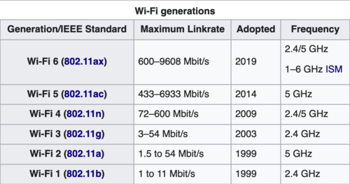](https://hvacknowitall.com/wp-content/uploads/2024/10/image-7.png)
*Evolution of Wi-Fi standards showing how data rates have increased with each generation – newer HVAC equipment often requires the latest standards for optimal performance. [Source: Wi-Fi 101 FAQ](https://evanmccann.net/blog/wifi-101/faq)*
Wi-Fi standards have evolved significantly, from 802.11b (11 Mbps) to 802.11a/g (54 Mbps), 802.11n (600 Mbps), 802.11ac (1.3 Gbps), and the latest 802.11ax or Wi-Fi 6 (9.6 Gbps). Each new generation brings improvements in speed, range, capacity, and efficiency.
[](https://hvacknowitall.com/wp-content/uploads/2024/10/image-6.png)
*Channel overlap between Bluetooth Low Energy and Wi-Fi in the 2.4GHz band – this explains why some smart HVAC tools may experience interference in buildings with busy Wi-Fi networks.*
PANs are even shorter-range networks, typically covering just a few meters around a person or device. Bluetooth is the most common PAN technology, used for wireless headphones, smartwatches, and device-to-device file transfers. Bluetooth and Wi-Fi share the 2.4GHz spectrum but have very different channel widths and modulation schemes – which affect their data rates and transmission distance.
Bluetooth comes in two main variants: **Bluetooth Classic** and **Bluetooth Low Energy** (LE). Bluetooth Classic is used for continuous, high-throughput applications like wireless audio, while Bluetooth LE is designed for low-power, intermittent data transfer, making it ideal for battery-operated sensors and wearables. Most HVAC smart probes use BLE for streaming data to your phone since they operate at low data rates.
**As an HVAC technician, you encounter Wi-Fi and Bluetooth devices daily – from configuring wireless thermostats to using smart tools in your tool bag. Understanding these technologies’ characteristics and limitations can speed up your workflow and help you avoid connectivity problems.**
### Wide Area Networks (WAN)
**Wide area networks** (WANs) cover large geographic areas, connecting multiple LANs and devices across cities, countries, or continents. The most common WAN technologies are cellular, fiber optic, cable, DSL, and satellite.
**Cellular networks**, operated by carriers like Verizon, AT&T, T-Mobile, and Sprint, provide wireless connectivity to mobile devices including smartphones, tablets, and IoT devices. They use licensed frequency bands and various technologies, from 2G (GSM, CDMA) to 3G (UMTS, EV-DO), 4G (LTE), and now 5G (NR). Each generation brings improvements in speed, latency, and capacity, enabling new applications like mobile broadband, video streaming, and large-scale sensor networks.
**Traditional wired WANs** use technologies like fiber optic, cable, and DSL to provide high-speed connectivity between fixed locations. Fiber optic offers the highest speeds and lowest latency but is expensive to deploy. Cable and DSL use existing coaxial and telephone lines, respectively, offering a good balance of speed and availability.
**Satellite networks**, traditionally used for TV broadcasting and remote connectivity, are becoming more significant with the development of low Earth orbit (LEO) constellations like SpaceX’s Starlink and Amazon’s Project Kuiper. These promise high-speed, low-latency internet to underserved areas, complementing terrestrial networks.
**As an HVAC technician, understanding the differences between these WAN technologies helps when troubleshooting remote monitoring and control systems, or when installing devices that require cellular or internet connectivity.**
### Machine-to-Machine (M2M) & Industrial Networks
**Machine-to-machine** (M2M) and industrial networks are specialized networks designed for connecting sensors, actuators, and controllers in industrial environments. They’re characterized by low power consumption, long range, and high reliability, often operating in challenging conditions like factories, warehouses, and outdoor installations.
Many M2M and industrial networks operate in the unlicensed ISM bands, using technologies like **LoRa**, **Zigbee**, and proprietary protocols. LoRa (Long Range) is a low-power wide-area network (LPWAN) technology enabling long-range communication (up to 10 km) with low data rates (up to 50 kbps). It’s commonly used for applications like smart metering, asset tracking, and environmental monitoring.
Zigbee is a short-range, low-power wireless mesh network protocol based on the IEEE 802.15.4 standard. It’s widely used in home automation, building automation, and industrial control systems. Zigbee devices can form self-organizing, self-healing mesh networks, making them resilient and scalable.
[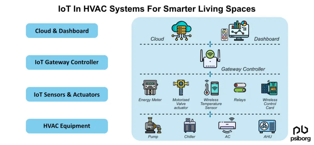](https://hvacknowitall.com/wp-content/uploads/2024/10/image-8.png)
*The layered architecture of a typical M2M network for HVAC applications – understanding these layers helps diagnose where communication problems might be occurring. [Source: IoT in HVAC Systems](https://psiborg.in/iot-in-hvac-systems-for-smarter-living-spaces/)*
In the HVAC world, you may encounter M2M and industrial networks in various applications, such as:
- Wireless thermostats and temperature sensors using Zigbee or proprietary protocols
- Building automation systems using BACnet or Modbus over wireless links
- Smart meters and energy monitoring devices using LoRaWAN or cellular IoT
- Wireless control systems for HVAC equipment using ISM band radios
**Understanding the characteristics and applications of these networks helps select the right technology for each application and troubleshoot issues related to range, interference, or interoperability.**
When working with wireless systems, there are several challenges and best practices to keep in mind, whether you’re installing a new system or troubleshooting an existing one.
### Safety
Safety should always be your top priority when working with wireless systems. Here are some key considerations:
- Always read the manual and follow the manufacturer’s instructions for safe installation and operation. If unsure, consult with the manufacturer or a qualified expert.
- Be aware of [the potential hazards of high-powered antennas](https://www.professionalroofing.net/Articles/The-risks-of-radiation--10-01-2010/1774), especially when working on rooftops. Cellular base stations, microwave links, and radar antennas can emit strong electromagnetic fields that can cause harm if you’re too close. Maintain a safe distance and avoid standing in front of active antennas.
- Comply with local building and safety codes, including regulations for antenna placement, cable routing, and grounding. Ensure that all installations are properly secured and weatherproofed.
- Use appropriate personal protective equipment (PPE) when working with wireless devices, including insulated gloves, safety glasses, and fall protection gear when working at heights.
[](https://hvacknowitall.com/wp-content/uploads/2024/10/HVAC-Tech-Guide-To-RF-Radiation.png)
*RF radiation safety guidelines – while most HVAC wireless equipment operates at safe power levels, it’s important to understand exposure limits when working near commercial transmitters.*
### Antenna Placement and Orientation
Proper antenna placement and orientation are critical for achieving optimal wireless performance. Here are some best practices:
- Try to provide as much clear space around antennas as possible. Avoid placing them near metal objects, walls, or other obstructions that can cause reflections, absorption, or interference.
- If mounting an antenna on a metal surface, use a ground plane or a magnetic mount to ensure proper grounding and radiation pattern (The device / antenna manual should have details on this).
- Orient antennas according to their radiation pattern and the desired coverage area. For omnidirectional antennas, mount them vertically for best horizontal coverage. For directional antennas, aim them towards the intended receiver or coverage area.
- In point-to-point links, ensure that the antennas are aligned with each other and have a clear line of sight. Use a compass, GPS, or antenna alignment tool to ensure precise aiming.
- [Keep antennas away from sources of electromagnetic interference (EMI),](https://library.e.abb.com/public/c5f39513fe6d49a88875f8b685aa4341/Application_guide_aspects_of_electromagnetic_compatibility.pdf) such as power lines, transformers, motors, and other radio equipment. If necessary, use shielded cables and connectors to minimize EMI pickup.
[](https://hvacknowitall.com/wp-content/uploads/2024/10/Screenshot-2024-10-16-at-1.37.35 PM.png)
*Common sources of electromagnetic interference on HVAC job sites – these can disrupt wireless signals and cause connectivity issues with smart equipment. [Source: ABB](https://library.e.abb.com/public/c5f39513fe6d49a88875f8b685aa4341/Application_guide_aspects_of_electromagnetic_compatibility.pdf)*
### Signal Strength and Quality
Achieving reliable wireless communication requires ensuring adequate signal strength and quality at the receiver. Here are some factors to consider:
- For Wi-Fi networks, use a channel planning tool to select the least congested channel and avoid overlapping with neighboring networks. In high-density environments, consider using the 5 GHz band or a Wi-Fi controller to manage channel assignments and power levels.
- For cellular IoT applications, ensure that the device has a clear view of the sky and is not obstructed by metal objects or thick walls. Use an external antenna if necessary to improve signal reception.
- For short-range applications like Bluetooth or Zigbee, ensure that the devices are within range of each other and there are no major obstructions between them. Use a mesh network topology to extend the range and provide redundancy.
- Advanced Concept: Use a site survey tool or spectrum analyzer to measure the signal strength (RSSI), noise floor, and interference levels in the intended coverage area. Ensure that the signal-to-noise ratio (SNR) is sufficient for reliable communication.
[](https://hvacknowitall.com/wp-content/uploads/2024/10/HVAC-Tech-Guide-To-RF-Attenuation.png)
*RF signal attenuation through common building materials – understanding these effects helps with optimal placement of wireless HVAC components.*
### Coexistence and Interoperability
Wireless systems often have to coexist with other devices and networks in the same environment. Here are some best practices for ensuring interoperability and minimizing interference:
- Follow the relevant standards and regulations for the frequency band and protocol you’re using. Ensure that your devices are certified for operation in your region.
- In multi-protocol environments, use devices that support multiple protocols and can switch between them seamlessly. For example, a gateway that supports both Zigbee and Wi-Fi can bridge the two networks and provide end-to-end connectivity.
Mastering wireless tech gives you a technical edge. Want a business edge too? Property.com’s exclusive ‘[Know Before You Go](https://mccreadie.property.com)’ tool provides critical homeowner insights *before* your visit permit history, home value, potential upgrade savings. Elevate your service and stand out. Join our invitation-only network of certified Pros. Limited spots per trade and region. Secure your advantage with Property.com today.
When working with wireless HVAC equipment, you’ll inevitably encounter connectivity problems. Here’s how to diagnose and solve the most common issues:
### Poor Signal Strength with Wireless Thermostats and Sensors
**Symptoms:** Intermittent connectivity, slow response times, or complete disconnection of wireless thermostats or temperature sensors.
**Troubleshooting Steps:**
1. Check the distance between the thermostat/sensor and its receiver or gateway. Most consumer-grade wireless thermostats have a practical range of 50-100 feet indoors, less if there are walls or other obstacles.
2. Look for physical obstructions. Metal ductwork, appliances, and reinforced concrete walls significantly reduce signal strength.
3. Verify battery levels in battery-powered devices. Low batteries often cause wireless connectivity problems before they fail completely.
4. Check for interference sources nearby. Cordless phones, microwave ovens, and baby monitors can all interfere with wireless devices, especially those operating in the 2.4GHz band.
**Solutions:**
– Relocate the thermostat or receiver to improve line-of-sight conditions
– Add a signal repeater or mesh network node to extend the range
– For Wi-Fi thermostats, consider connecting them to the 5GHz network instead of 2.4GHz if they support it
– Shield or relocate interference sources
### Bluetooth Tool Connectivity Problems
**Symptoms:** Unable to connect your phone to Bluetooth-enabled tools like digital manifolds or smart probes, or frequent disconnections during use.
**Troubleshooting Steps:**
1. Ensure Bluetooth is enabled on both devices and they’re within range (typically 30 feet for BLE devices).
2. Check if the tool’s battery is adequately charged.
3. Verify that the tool isn’t already connected to another device (many Bluetooth devices can only connect to one master device at a time).
4. For Android users, check location permissions, as Bluetooth scanning often requires location access.
**Solutions:**
– Reset the Bluetooth connection by turning Bluetooth off and on again on both devices
– Force-close and restart the app
– Forget/unpair the device and re-pair it
– Update the app and firmware on both devices
– Use a Bluetooth range extender for difficult environments
### Cellular and Wi-Fi Remote Monitoring Issues
**Symptoms:** Unable to remotely access building automation systems or HVAC monitoring equipment.
**Troubleshooting Steps:**
1. For cellular connections, check signal strength at the installation location. Look for at least 2-3 bars of signal strength.
2. For Wi-Fi, verify that the HVAC equipment is still connected to the network and has a valid IP address.
3. Check if other devices on the same network can connect to the internet.
4. Verify that the monitoring service is operational (check service status pages or contact the provider).
**Solutions:**
– For cellular devices, consider installing an external antenna or signal booster
– For Wi-Fi devices, move the router or add mesh network extenders
– Check and update firewall settings that might be blocking the connection
– Verify that service subscriptions are active and paid
### Security Considerations
As HVAC systems become increasingly connected, security becomes more important:
- Always change default passwords on wireless equipment, using strong, unique passwords
- Keep firmware updated on all networked devices to patch security vulnerabilities
- For commercial installations, consider using a separate network (VLAN) for HVAC and building controls
- Be wary of unnecessary open ports or services running on networked HVAC equipment
- Document all wireless devices installed for future reference and security audits
### When to Call for IT Assistance
While many wireless issues can be resolved with basic troubleshooting, some situations warrant professional IT help:
- Complex enterprise Wi-Fi environments with managed access points
- Suspected network security breaches or unauthorized access
- VPN configuration for secure remote access
- Integration with advanced building management systems
- Custom firewall or routing configurations
Remember that modern HVAC systems often sit at the intersection of mechanical, electrical, and information technology. Knowing when to collaborate with IT professionals can save time and ensure optimal system performance.
## Wrapping It All Up
Wireless technology has fundamentally transformed the HVAC industry, creating both new opportunities and challenges for technicians. The knowledge in this guide gives you a strong foundation for working with connected equipment and troubleshooting wireless issues effectively.
Key takeaways to remember:
- The wireless spectrum includes a range of frequencies, each with unique characteristics that determine their ideal applications in HVAC systems
- Antenna placement and orientation significantly impact wireless performance – small adjustments can make big differences
- Signal interference and attenuation through building materials are common causes of connectivity problems
- Modern HVAC tools and equipment use multiple wireless technologies (Wi-Fi, Bluetooth, cellular, and proprietary protocols) that must coexist
- Basic wireless troubleshooting skills can save significant time on service calls involving connected equipment
As wireless technologies continue to evolve, staying current with the fundamentals will become increasingly valuable. New standards like Wi-Fi 6, 5G, and advanced IoT protocols will enable more sophisticated control, monitoring, and diagnostic capabilities in tomorrow’s HVAC systems.
For technicians willing to build expertise in this area, wireless technology represents a valuable specialization that bridges traditional HVAC knowledge with the growing demand for smart building solutions. Consider seeking additional training or certification in building automation systems and wireless networking to further enhance your professional capabilities.
**As an HVAC technician, having a practical understanding of wireless principles, common challenges, and best practices will help you install, configure, and troubleshoot wireless devices more effectively. When facing complex networking issues, don’t hesitate to consult with manufacturers, system integrators, or qualified IT professionals who can provide specific guidance for the equipment you’re working with.**
document.addEventListener('DOMContentLoaded', function() {
var links = document.querySelectorAll('a[href="https://mccreadie.property.com"]');
links.forEach(function(link) {
link.addEventListener('click', function(event) {
if (typeof gtag === 'function') {
gtag('event', 'click', {
'event\_category': 'Outbound Link',
'event\_label': window.location.pathname,
'transport\_type': 'beacon'
});
}
});
});
});
{
"@context": "https://schema.org",
"@type": "TechArticle",
"headline": "The Complete HVAC Technician's Guide to Wireless Communications: Essential Knowledge for Modern Service",
"description": "Learn the essentials of wireless technology for HVAC professionals. Master the fundamentals of RF, antennas, and networks to troubleshoot connected equipment.",
"author": {
"@type": "Person",
"name": "HVAC Know It All"
},
"publisher": {
"@type": "Organization",
"name": "HVAC Know It All",
"logo": {
"@type": "ImageObject",
"url": "https://hvacknowitall.com/wp-content/uploads/2022/03/cropped-hvacknowitall-favicon-32x32.png"
}
},
"datePublished": "2024-10-16",
"image": "https://hvacknowitall.com/wp-content/uploads/2024/10/image-edited.png",
"mainEntityOfPage": {
"@type": "WebPage",
"@id": "https://hvacknowitall.com/an-hvac-technicians-guide-to-wireless-communications"
},
"articleSection": "Technical Guides",
"keywords": "HVAC, wireless communications, RF, antennas, Wi-Fi, Bluetooth, troubleshooting",
"definedTermSet": [
{
"@type": "DefinedTerm",
"name": "Electromagnetic Wave",
"description": "A wave consisting of electric and magnetic fields oscillating perpendicular to each other and to the direction of propagation."
},
{
"@type": "DefinedTerm",
"name": "Frequency",
"description": "The number of cycles or oscillations a wave completes per second, measured in Hertz (Hz)."
},
{
"@type": "DefinedTerm",
"name": "Amplitude",
"description": "The maximum displacement of a wave from its equilibrium position, measuring the strength or intensity of the wave."
},
{
"@type": "DefinedTerm",
"name": "Wireless Spectrum",
"description": "The complete range of electromagnetic frequencies used for wireless communications."
},
{
"@type": "DefinedTerm",
"name": "ISM Band",
"description": "Industrial, Scientific, and Medical radio bands that are unlicensed and commonly used for wireless devices."
},
{
"@type": "DefinedTerm",
"name": "Omnidirectional Antenna",
"description": "An antenna that radiates equal power in all directions in one plane."
},
{
"@type": "DefinedTerm",
"name": "Directional Antenna",
"description": "An antenna that radiates power more effectively in one or more directions."
},
{
"@type": "DefinedTerm",
"name": "Bluetooth Low Energy",
"description": "A wireless personal area network technology designed for low power consumption and short-range communication."
},
{
"@type": "DefinedTerm",
"name": "Wi-Fi",
"description": "A technology for wireless local area networking based on the IEEE 802.11 standards."
}
]
}
--------------------------------------------------
# ID: 5149
## Title: Pressure Testing Refrigeration Systems: Essential Procedures and Best Practices
## Type: blog_post
## Author: Julian Finbow
## Publish Date: 2024-09-08T20:35:10
## Word Count: 3028
## Categories: Refrigeration, HVAC Maintenance
## Tags: best practices, bulk pack, chillers, gas, inspection, leak testing, nitrogen, pressure, pressure test, refrigeration systems, standards, test procedures, vacuum
## Permalink: https://hvacknowitall.com/blog/pressure-testing-refrigeration-systems
## Description:
## Why Pressure Test?
When construction or repair of a refrigeration system is complete, it is standard procedure to perform a **Pressure Test**. Pressure Testing describes the practice of pneumatically testing the piping and components of the system by adding a test fluid until the desired test pressure is met.
The reason a Pressure Test is done is to ensure there are no leaks in the system before the vacuum is pulled and refrigerant is charged. In this article, I will cover important practices for Pressure Testing as it applies to different sizes and types of refrigeration systems, from small residential units to large industrial applications.

The upper bounds of your test will be determined by the Maximum Operating Pressure of the refrigeration system you are testing. The two pieces of information you need to determine this are the Refrigerant Type for the system, and the Saturated Condensing Temperature (**SCT**) the system is intended to operate at. (1.25)(**Max Operating Pressure (MOP)**) is common practice for testing refrigeration systems, aligning with specifications from [**ASME**](https://www.asme.org/) (**American Society of Mechanical Engineers**), [**TSSA**](https://www.tssa.org/) (**Technical Standards and Safety Authority**) and [**CSA**](https://www.csagroup.org/) (**Canadian Standards Association**).
ASME are American standards which are internationally accepted and specified, while TSSA and CSA standards are relative to my work area of Toronto, Canada. Refrigeration Systems in this area are constructed, repaired, and tested as per [**CSA B52 Mechanical Code**](https://www.csagroup.org/store/product/2702258/), and have systems field inspected by TSSA when required. PSIG (Pounds Per Square Inch Gauge) is the commonly used pressure increment in this region, so these are the units I will use throughout the rest of this article.
> **Note**: The industry also uses **kPa** (kilopascal) (6.895kPa = 1 PSI), as well as **Bar** on CO2 systems due to their high pressures (14.5PSI = 1 Bar).
The testing fluid most appropriate is **Nitrogen** ([atomic number N7](https://en.wikipedia.org/wiki/Nitrogen)). Most of the air that we breathe is nitrogen: air’s composition can be seen below.
> **Note**: It is **never** advisable to hydrostatically test a refrigeration system using water.

An illustration of Dalton’s law using the gasses of air at sea level (Source: [Wikipedia](https://en.wikipedia.org/wiki/Dalton%27s_law#))
The industry uses “Food Grade” Nitrogen for Refrigeration System Pressure Testing: it is clean of contaminants, and most importantly, very low in moisture content.
> **Note**: Medical Grade Nitrogen goes a step further, being extremely dry.
Moving on to the format of Nitrogen and getting it into the system, the next image below is from Josef Gas, and shows us [the different nitrogen bottle sizes available](https://josefgases.com/gas/nitrogen/food/) on the market.
The bottle, or “Bulk Pack” (16 Nitrogen bottles tied together in parallel with a common outlet) is then connected to a Nitrogen Regulator. There are Standard Nitrogen Regulators, and High Pressure Nitrogen Regulators.
Their difference is a max regulator inlet pressure (from the [Nitrogen Bottle](https://hvacknowitall.com/blog/nitrogen-tank-and-gauge-precautions)) of 4000PSIG, or 6000PSIG (see image above). Respectively, they also have different Delivery Pressures available on the outlet side of the regulator (to the system), represented on their gauge.
These 2 classes of regulators have different thread patterns on them, to avoid the possibility of connecting a Standard Regulator to a High Pressure Bottle (or Bulk Pack) where a failure would occur.

When working with high-pressure nitrogen, safety should be your top priority. Always follow these essential precautions:
1. **Always wear safety glasses** when working with pressurized systems
2. **Secure nitrogen cylinders** in an upright position to prevent tipping
3. **Never use damaged regulators or gauges** – inspect equipment before each use
4. **Release pressure slowly** to avoid dangerous rapid decompression
5. **Use appropriate regulators** for the pressure rating of your nitrogen source
6. **Keep cylinders away from heat sources** and direct sunlight
7. **Transport cylinders properly** with valve protection caps in place
8. **Never exceed the test pressure** specified for the system components
Remember that high-pressure nitrogen can cause serious injury if mishandled. Always approach pressure testing with care and follow all safety protocols.
Starting with Small Refrigeration Systems, we will categorize this as anything under “3 tons or less of refrigeration, or 5 tons or less of Air conditioning” – as per **ORAC** (Ontario Refrigeration & Air Conditioning, [paragraph 3 of this webpage on brazing](https://orac.ca/resources/brazing-certifications/index.html)). It is stated here that a TSSA Inspection/Pressure Test Witness is **not** required below these system capacities.
For Small Systems, consider the piping and components all being in a local area. This would include:
- Roof Top Units
- Split systems of any type: Furnace, Ductless Split, Window Shaker (so long as they do not have very long piping runs)
- Appliances (Fridges/Freezers of any type)
- Self Contained Units (Absorption Systems, Heat Recovery Systems, [Heat Pumps](https://hvacknowitall.com/blog/geothermal-heat-pump-basics))
- Small Critically Charged Freezers and Coolers
> **Note**: Chillers straddle between a Small and Large System, as their Refrigeration System is contained within one area, but is however large capacity, well above the ORAC tonnages stated.
Pressure Testing a Small System is usually a straightforward, simple procedure (see image below of a Ductless Split). If all system components and piping can be accessed in one or two areas, it simplifies the process/time taken of leak checking and completing a Pressure Test. Not having to schedule TSSA for inspection(s) also makes the install or system repair easier to plan and schedule.
A popular residential air conditioning refrigerant is R134a, and a common operating point for it is 120f **Saturated Condensing Temperature (SCT)**. The SCT is the basis of the highest temperature, and pressure realized in a system. To find the pressure related to this Saturated Temperature, utilize a Pressure Temperature Chart (such as [Bitzer Refrigerant Ruler](https://www.bitzer.de/au/en/tools-archive/apps/)):
1. Take your SCT of 120f to the Pressure Temperature Chart
2. Find the “Saturated Condensing Pressure” of 171.1PSIG
3. Following the previously mentioned equation: (1.25)(MOP), we get (1.25)(171.1PSIG) = **213.875PSIG**. Round this to **214PSIG**
So, *214PSIG is the max pressure we can achieve during testing*. This is commonly rounded up to 225PSIG or 250PSIG for this refrigerant, as this is still well below max pressure ratings for most components. Be wary of exceeding pressure ratings of low side components however, such as a **Low Pressure Cut-Out (LPCO)**. If low side components have lower pressure ratings than the intended max test pressure, it may be necessary to isolate the high side from the low side of the system and run two separate tests.
For a system of this size, here is a plan to follow for Pressure Testing. This example is for a system which is “Flat” (empty / 0PSIG). We will use 250PSIG as our Final Test Pressure.
- Ensure all system valves are open. Ensure safety glasses are worn.
- Add nitrogen to achieve 50% of the Final Test Pressure: 125PSIG. This can be done by connecting the nitrogen bottle to a regulator, and attaching the regulator to a refrigeration manifold which is connected to the system. Alternatively, the nitrogen bottle/regulator can be connected directly to the system (with an isolation valve in between), and a pressure gauge (preferably digital, for accuracy) attached directly to the system.
- Quickly check the indoor unit/piping by listening (you can hear leaks at this pressure if the work area is quiet), and soap test using a Non-Corrosive Soap such as Big Blu. Ensure to soap more common leak points e.g schrader valves/caps, and flare connections.
- Quickly check the outdoor unit/piping with the same considerations as above. Ensure that all gauges/fittings/hoses that you are using for the pressure test are also soap tested.
- If no leaks are found, you are ready to bump up to your final test pressure.
> **Note**: It is good practice to perform your first soap/leak check at this lower pressure to start. If nothing else, this would save Nitrogen in the case that you find a leak at the initial lower pressure (this would also save a considerable amount of time on a Large System).
- Increase the system pressure to 250PSIG and start a timer for 1 hour. More time under test is preferred, (more on this later) but 1 hour is common practice, as this allows you to begin Evacuation sooner.
> **Note**: Your “Vacuum Test” and “Decay Test” will add further certainty that your system is free from leaks.
- *Thoroughly* check the indoor unit/piping by listening, and soap testing everything: all piping and component connection points of any kind. An Inspection Mirror and Flashlight are a great help to be efficient and confident. You are looking to see if any soap is growing bubbles, i.e a “Beard”. Very small leaks may need to be realized after the soap has sat on the leak for 15 minutes or more. As they say, *no bubbles, no troubles*.
- *Thoroughly* check the outdoor unit with the same considerations as above. Again, ensure that all gauges/fittings/hoses that you are using for the pressure test are also soap tested.
- If no leaks are found, and the gauge has maintained 250PSIG, the pressure can now be blown off the system.
> **Note**: Release the pressure slowly whenever possible to avoid noise. If no one else is within earshot and you would like to blow the pressure off quicker: ensure the blow off point is stable (the hose is not loose) and wear appropriate hearing protection.
- If evacuation is your next step, you want to time the end of your nitrogen blow down so that you have about 1-2PSIG remaining in your system and begin to pull the vacuum at this time.
> **Note**: If you blow a system down to 0PSIG, air will make its way back into the system through the open port. Just by adding and removing nitrogen, you have already removed a large volume of air from your system.
- If you will not evacuate until later, blow down your system to 10-20PSIG. This is a common Safe Holding Charge Pressure, which keeps the system positive so that air does not enter the system.

Large Systems will be greater than 3 tons of refrigeration, or 5 tons air conditioning. I will forego categorizing “Medium” Systems for conciseness. A Large System’s physical size/layout comes down to there being multiple locations which require inspection during the pressure test. There can be multiple people, and multiple hours or days put into pressure testing a Large System.
The pressure testing may be done in multiple “Phases” during construction, as main portions of the systems are completed. Access to roofs, penthouses, valve stations, interstitial spaces, engine rooms, high ceiling hung evaporators and other components may be required. Use of scissor lifts, boom lifts, and ladders are also common to access all points to be soap tested. Large System types include:
- Supermarkets
- Ice Rinks
- Industrial Food Process Plants
- Cold Storage Plants
- Mining Refrigeration Systems
- Commercial Heat Pumps and Heat Recovery Systems
> **Note**: Large Homes also fall into this category if their system tonnage requires TSSA Inspection. Homes can have quite complex **VRF Systems (Variable Refrigerant Flow)** in them, tied into a home automation system much like a commercial **Building Automation System (BAS).**

To ensure a system is leak free, a similar process is followed for a Small System or Large System. There are however many planning considerations which are unique to systems which require TSSA inspection. This is true in service/repair applications, but I will focus on new construction in this section for simplicity.
> **Note**: TSSA Inspections have *extremely variable* degrees of leniency or strictness, so I will list *best practices* below.
- Material must be ordered, received, and inspected in accordance with required Material Specifications. Canadian Registration Numbers, Mill Test Reports, Data Reports, and Material Designations which match paperwork must be clearly stenciled/ stamped onto piping and fittings from the manufacturers, and circled or confirmed by the person who receives it on site. This is a required **QC (Quality Control)** Process.
- TSSA will visit a very large project up to three times for a single “Phase” of the project. This includes a “Pre-Pipe Inspection,” another visit to confirm procedures are followed during construction, and a final visit for the TSSA Inspector (or person authorized on their behalf) to witness the Final Pressure Test.
- These above considerations require planning ahead for material order and receival, as well as completion dates for significant sections of the project. Organization of material, and its paperwork is paramount to being successful in a TSSA Inspection, on top of completing a successful Pressure Test.
There are some things which are unique to testing Large Systems compared to a Small System. These are both procedural, and to ensure inspection requirements are met. Here are the points unique to Large Systems:
- The Final Test Pressure must remain below 10% of any Relief Valve which will be part of the Pressure Test. Relief Valves may open 10% above or below their rated pressure. Another less preferred practice is removal of Relief Valves from the system until the Pressure Test is completed.
- The test gauge must be calibrated (annually), and the Certificate of Calibration must be on-hand.
- Nitrogen Bulk Packs may be used. A Bulk Pack is 16 Nitrogen bottles tied together in parallel with a common outlet. Each bottle still has its own handle, which allows the Refrigeration Mechanic to strategically open/close individual bottles, depending on his strategy to optimize pressure delivery to the system. This can be a bit nuanced, so I will not go into detail.
- High Pressure Nitrogen Bottles (or High Pressure Bulk Packs) may be used instead of standard pressure nitrogen. For ammonia systems, high pressure bulk packs are used for fast/efficient delivery of nitrogen to the system: ammonia (R-717) refrigeration systems are only tested to 250PSIG. For CO2 Systems, High Pressure Nitrogen bottles/Bulk Packs are used due to the high operating pressures, therefore required high test pressures well over 1000PSIG for a Transcritical system. Ensure that you have a High Pressure Nitrogen Regulator on hand for use with these Nitrogen Bottles or Bulk Packs.
- Large diesel or gas air compressors may be used in ammonia systems to get the initial test pressure up to around 110PSIG where the Air Compressor will max-out in increasing pressure. If at this pressure the first soap test and inspection show no leaks, the pressure will be bumped up with a high pressure bulk pack to its Final Test Pressure. The downside of this method is that air is added to the system. This is a trade-off of cost of the test fluid (compressor rental is cheaper than buying nitrogen), to adding moisture to the system. This partial use of air to test will cause a longer evacuation time, with more vacuum pump oil changes.
> **Note**: It is common to evacuate systems of this type for multiple days, at multiple locations before charging.
- A small leak on a Small System should be found within 1 hour. A small leak on a Large System would have no, or virtually no affect on the gauge over 1 hour. This is why a test time of 24 hours is more suitable. The 24 hour test time is also required by TSSA.
- Ambient Temperature of the Test Gauge location must be measured at time the 24 hour test period begins. If this is in the afternoon and the Test Gauge is outside, the next morning the gauge pressure could be lower, and then rise again the next day back to the Final Test Pressure as the outdoors warms up. This is due to the Temperature Pressure Relationship of Nitrogen gas.
> **Note**: Nitrogen is more stable than air in this respect, as its pressure is less influenced by temperature change compared to air. The [HVAC School Application’s “Nitrogen Pressure” Tool](https://hvacrschool.com/apps-page/) (see final image) is a great way to be confident with a pressure drop overnight if ambient conditions have cooled down. You can enter starting pressure/temperature, then enter the new temperature from next day to see what your pressure should be. You may realize you have a leak you did not find, or that the pressure drop is indeed relative to the drop in temperature.

Following best practices like detailed pressure testing sets you apart. Elevate your professional standing further with Property.com. Our exclusive, invitation-only network connects top-tier HVAC contractors with homeowners seeking quality and reliability. Boost your credibility and SEO with a custom Property.com subdomain, access critical homeowner data with our ‘[Know Before You Go](https://mccreadie.property.com)’ tool, and benefit from comprehensive reputation management. Limited spots available per trade and region. Secure your advantage and lock in early adopter rates today.
## Conclusion
Pressure Testing is an essential component of both service/repair work and new construction of refrigeration systems. While conceptually straightforward, mastering the process requires knowledge and practice to improve efficiency and ensure system integrity. For complete system commissioning, be sure to check out our upcoming articles on [evacuating refrigeration systems](https://hvacknowitall.com/blog/evacuating-refrigeration-systems) and [charging refrigerant](https://hvacknowitall.com/blog/charging-refrigeration-systems).

Looking for more HVAC insights? Tune into our [podcast](https://hvacknowitall.com/podcasts) and explore additional [blog articles](https://hvacknowitall.com/blog) for expert tips and the latest industry updates. Stay informed and ahead of the curve with HVAC Know It All!
document.addEventListener('DOMContentLoaded', function() {
var links = document.querySelectorAll('a[href="https://mccreadie.property.com"]');
links.forEach(function(link) {
link.addEventListener('click', function(event) {
if (typeof gtag === 'function') {
gtag('event', 'click', {
'event\_category': 'Outbound Link',
'event\_label': window.location.pathname,
'transport\_type': 'beacon'
});
}
});
});
});
{
"@context": "https://schema.org",
"@type": "TechArticle",
"headline": "Pressure Testing Refrigeration Systems: Essential Procedures and Best Practices",
"description": "Learn industry-standard procedures for pressure testing refrigeration systems, from small residential units to large commercial systems, including nitrogen safety, TSSA requirements, and best practices.",
"author": {
"@type": "Organization",
"name": "HVAC Know It All"
},
"publisher": {
"@type": "Organization",
"name": "HVAC Know It All",
"logo": {
"@type": "ImageObject",
"url": "https://hvacknowitall.com/wp-content/uploads/2022/11/hvacknowitall-red-logo-favicon.png"
}
},
"image": "https://hvacknowitall.com/wp-content/uploads/2024/08/1\_analog\_refrigeration\_gauges-1024x424.png",
"datePublished": "2024-08-01",
"proficiencyLevel": "Expert",
"articleSection": "Refrigeration",
"keywords": [
"pressure testing",
"refrigeration systems",
"nitrogen",
"TSSA inspection",
"HVAC procedures",
"PSIG",
"small refrigeration systems",
"large refrigeration systems"
]
}
--------------------------------------------------
# ID: 5024
## Title: Evaporator Delta T vs. Temperature Difference (TD): Essential HVAC Measurements Explained
## Type: blog_post
## Author: Gary McCreadie
## Publish Date: 2024-06-16T21:18:57
## Word Count: 1083
## Categories: Air Conditioning, Heat Pumps
## Tags: None
## Permalink: https://hvacknowitall.com/blog/delta-t-vs-temperature-difference
## Description:
## **Understanding Critical HVAC Measurements**
Many HVAC helpers, apprentices, and even experienced technicians get tripped up when discussing Delta T versus Temperature Difference (TD). These terms are often used interchangeably or confused with one another, leading to diagnostic errors and miscommunication. This guide will clarify the important distinctions between these two critical measurements and explain how each contributes to proper system diagnosis.
In both examples below, we’ll focus on the evaporator to provide a clear, simplified explanation in the context of air conditioning systems.
In HVAC (Heating, Ventilation, and Air Conditioning) systems, “Evaporator TD” and “Evaporator Delta T” are terms often used to describe different temperature differentials associated with the evaporator. Understanding the distinction between these terms is important for diagnosing system performance and efficiency.

This typically refers to the difference in temperature between the air entering the evaporator and the refrigerant inside the evaporator coil.
**The formula for Evaporator TD is:** Evaporator TD = Air Entering Temperature – Evaporator Refrigerant Temperature.
This measurement is useful for assessing the heat transfer performance of the evaporator. A typical value for Evaporator TD will depend on the system design but usually is approximately 35F (20C) for air conditioning systems.
For example, If the return air to the evaporator coil is 75F and the SST (saturated suction temperature) is 40F, there is a 35F evaporator temperature difference or TD.

This refers to the difference in temperature of the air before and after it passes over the evaporator coil.
**The formula for Evaporator Delta T is:** Evaporator Delta T = Air Entering Temperature – Air Leaving Temperature.
This measurement indicates how much heat is being removed from the air by the evaporator.
Typical values for Evaporator Delta T will vary according to system specifics, but common ranges are 15F to 20F (8C to 11C).
Air that contains more moisture will have a lower Delta T as the coil is doing a lot of latent heat removal. Air that contains less moisture will have a higher Delta T as it’s doing more sensible heat removal.
| Aspect | Evaporator TD | Evaporator Delta T |
| --- | --- | --- |
| **Definition** | Temperature difference between entering air and refrigerant | Temperature change in air before and after evaporator |
| **Formula** | Air Entering Temp – Refrigerant Temp | Air Entering Temp – Air Leaving Temp |
| **Typical Value** | ~35F (20C) | 15-20F (8-11C) |
| **What It Shows** | Heat transfer efficiency between air and refrigerant | Total cooling effect on passing air |
| **Measurement Points** | Return air and evaporator coil | Return air and supply air |
Evaporator TD focuses on the temperature difference between the air and refrigerant. Evaporator Delta T focuses on the temperature change of the air as it passes through the evaporator.
Evaporator TD is more about the efficiency and effectiveness of heat transfer between the air and refrigerant. Evaporator Delta T is concerned with how much cooling effect the evaporator is providing to the air.
### **Diagnostic Applications**
Understanding these measurements allows for precise system diagnosis:
- **Low Evaporator TD** (less than 30F): May indicate refrigerant overcharge, dirty evaporator coil, or excessive airflow
- **High Evaporator TD** (more than 40F): Could suggest refrigerant undercharge, restricted metering device, or insufficient airflow
- **Low Delta T** (less than 15F): Often points to low refrigerant charge, airflow issues, or dirty coil
- **High Delta T** (more than 22F): May indicate reduced airflow, dirty filter, or low humidity conditions
By correctly interpreting these values together, you can pinpoint issues more accurately than with either measurement alone.
Evaporator TD involves measuring air entering temperature and refrigerant temperature. Evaporator Delta T involves measuring air entering and air leaving temperatures.
To accurately measure these values, you’ll need:
1. **Digital Manifold Gauge Set**: For measuring refrigerant pressure/temperature
2. **Psychrometer or Digital Thermometer**: For accurate air temperature readings
3. **Temperature Clamps**: For measuring pipe temperatures
4. **Infrared Thermometer**: For non-contact temperature readings
Proper positioning of temperature probes is critical – measure return air before the filter and supply air at least 18 inches from the coil for accurate readings.
For a detailed visual explanation of these concepts, watch this video:
By mastering these temperature measurements, you can identify underlying system issues with confidence and precision. This knowledge translates directly into legitimate repair opportunities for your customers.
Understanding both TD and Delta T measurements leads to better diagnostics and optimization of HVAC systems. For instance, if you find a lower-than-expected Evaporator TD alongside an abnormal Delta T, you can quickly narrow down potential issueswhether it’s refrigerant levels, airflow restrictions, or component failures.
This diagnostic precision not only improves your technical credibility but also helps customers understand the value of necessary repairs, increasing your service value and customer satisfaction.
Mastering diagnostics like Delta T vs. TD sets you apart. Elevate your business further with Property.com’s exclusive network. Access homeowner insights with our ‘[Know Before You Go](https://mccreadie.property.com)’ tool, boost your SEO with a premium subdomain, and manage your reputation effortlessly. Limited spots available per trade/region. Become a certified Property.com Pro today.
## **Conclusion**
Terminology in HVAC is crucial for accurate diagnostics and effective communication. Understanding the difference between Evaporator TD and Delta T allows you to properly assess system performance and identify potential issues.
By correctly measuring and interpreting these values, you can ensure systems run efficiently and effectively, providing optimal comfort and energy savings for your customers while identifying legitimate repair opportunities.
Remember: TD measures the temperature difference between air and refrigerant, while Delta T measures the temperature change of air passing through the coil. This fundamental distinction is key to becoming a more skilled and effective HVAC professional.
document.addEventListener('DOMContentLoaded', function() {
var links = document.querySelectorAll('a[href="https://mccreadie.property.com"]');
links.forEach(function(link) {
link.addEventListener('click', function(event) {
if (typeof gtag === 'function') {
gtag('event', 'click', {
'event\_category': 'Outbound Link',
'event\_label': window.location.pathname,
'transport\_type': 'beacon'
});
}
});
});
});
{
"@context": "https://schema.org",
"@type": "TechArticle",
"headline": "Evaporator Delta T vs. Temperature Difference (TD): Essential HVAC Measurements Explained",
"description": "Learn the critical difference between Evaporator Delta T and Temperature Difference (TD) in HVAC systems. Master these measurements to improve diagnostics, efficiency, and repair accuracy.",
"image": [
"https://hvacknowitall.com/wp-content/uploads/2024/06/R410A-Slider-View-1024x1024.jpg",
"https://hvacknowitall.com/wp-content/uploads/2024/06/Evaporator-air-flow-.jpg"
],
"author": {
"@type": "Organization",
"name": "HVAC Know It All"
},
"publisher": {
"@type": "Organization",
"name": "HVAC Know It All",
"logo": {
"@type": "ImageObject",
"url": "https://hvacknowitall.com/wp-content/uploads/2023/08/HVACKIA-150-X-150.png"
}
},
"about": {
"@type": "Thing",
"name": "HVAC diagnostics and measurements"
},
"educationalUse": "Technical Reference",
"audience": {
"@type": "Audience",
"audienceType": "HVAC Professionals"
}
}
--------------------------------------------------
# ID: 4827
## Title: Understanding Refrigerant Gas Volume: Key Concepts for HVAC Professionals
## Type: blog_post
## Author: Julian Finbow
## Publish Date: 2024-05-27T19:07:36
## Word Count: 1693
## Categories: Refrigerants
## Tags: None
## Permalink: https://hvacknowitall.com/blog/what-size-is-your-gas
## Description:
## Understanding Refrigerant Gas Volume in HVAC Systems
When troubleshooting or optimizing mechanical cooling systems, a critical but often overlooked factor is refrigerant gas volume. This property significantly impacts system performance, efficiency, and compressor operation.
Gas volume refers to the amount of space that refrigerant occupies per pound of weight (expressed in ft/lb). In professional terms, this is known as **Specific Volume (SV)**. The “lighter and fluffier” the gas is, the more of it your compressor must pump to achieve **1 Ton of Cooling (12,000 BTU/hour)**, directly affecting system efficiency and capacity.
This concept becomes particularly important when analyzing refrigerant conditions in the suction line. Different applications require different gas volumes, and understanding these relationships is essential for proper system design, troubleshooting, and optimization.
An often overlooked consideration in a mechanical cooling system is gas volume. Gas volume can describe the cubic footage of space that a gas is taking up per pound of the gas by weight (expressed in ft/lb).
Consideration of refrigerant gas volume is most important when looking at refrigerant conditions in the suction line. The ‘lighter and fluffier’ (coined by the author) that the gas is, the more of it your compressor must pump to accomplish **1 Ton of Cooling (12,000 BTU/hour)**.
More specifically, volume is referred to as **Specific Volume (SV)**. For example, a Reciprocating Booster Compressor (1st of 2 compression stages) must have physically large cylinders to pump enough of the low temperature/high specific volume gas required to achieve its capacity.
Note that Booster Compressors pull a low **Saturated Suction Temperature (SST)** gas, perhaps -20F SST, which has a high **Specific Volume**. A gas with high Specific Volume is represented on the left side of the image below.

The opposite of specific volume is Density. **Density (D)** can be described as the weight of refrigerant in pounds per cubic foot of space the gas is taking up (expressed in lb/ft). Air conditioning compressors pull suction from a high-temperature gas around 40F SST, which is a very dense gas.
Using a Reciprocating Compressor again, its cylinders will be much smaller. This is for two reasons:
1. It needs to move less total refrigerant (since it is dense) to accomplish e.g. 1 Ton of Cooling
2. If the cylinders were large, the Compressor would easily pull a high motor current as this dense (heavy and sluggish) gas takes more work to compress
The right side of the image above represents a gas with high density. Different Compressors exist for different desired suction temperatures. When they’re represented mathematically, density and specific volume are reciprocal (image below).

For any Compressor’s operation, the importance of gas volume can be clearly shown on a Pressure Enthalpy Diagram. The remainder of this article will take for granted that the reader understands Pressure Enthalpy Diagrams and how refrigeration systems are plotted on them.
To learn these details or brush up on them, please visit [Sporlan Pressure Enthalpy Diagram](https://www.parker.com/content/dam/Parker-com/Literature/Sporlan/Sporlan-pdf-files/Sporlan-pdf-Miscellanous/5-200.pdf). This PDF is a great resource, which I reference regularly during classes on **Pressure Enthalpy (PE)**.
### Danfoss Cool Selector 2
The PE Diagrams shown in the remaining images are from the [Danfoss Cool Selector 2](https://www.danfoss.com/en/service-and-support/downloads/dcs/coolselector-2/) application. This free tool can be downloaded or viewed online.
[Here is a video](https://www.youtube.com/watch?v=IFBlnoDeeeg) that shows (at 1:32) how to access PE Diagrams from Cool Selector. Within the application, they are referred to as “p-h” diagrams, with “h” representing enthalpy. You can also plot Compressors/systems within the app (shown later in the video), select equipment, perform heat load calculations, and more.

Picture your customer making a request to change the operating conditions of their cooler. They instead would like to run their cooler as a freezer. Something like this can be done by reducing the **Saturated Suction Temperature (SST)** of the Compressor which pulls suction on the refrigerated space’s evaporator.
If the **Low Pressure Cut-Out (LPCO)** is the Compressor operating control, this switch could be operated to have the Compressor turn off at a lower pressure corresponding to the new desired SST. To see the ill effects this could cause, we can use the Pressure Enthalpy Diagram. In the image below, an SST of 40F and an SST of 0F are both referenced on the 100% Saturated Vapour Line.
Their Specific Volume values (expressed in ft/lb) are illustrated by the lines extending to the right side of the graph. It can be gleaned from this that a reduction in SST causes an increase in the Specific Volume of the refrigerant.
The characteristics of Saturated Vapour can be remembered by comparing them to freezing water: as the water freezes, it continues to expand. Mechanics and operators need to consider this increased gas specific volume when lowering the Compressor SST.
### Negative Effects of Reducing SST Due to Increased Specific Volume
- **Increased Specific Volume:** Must pump more refrigerant per ton of cooling
- **Increased gas entropy:** Less efficient compression
- **Reduced hermetic motor cooling:** Though the gas is ‘colder’, its large volume results in less winding cooling
- **Reduced volumetric efficiency**
- **Reduced Compressor capacity**
- **Reduced Coefficient of Performance (COP)**
If Saturated Condensing Temperature (SCT) is held constant:
\* **Increased compression ratio**
\* **Higher discharge gas temperatures**
\* **Higher oil temperatures**

A **Thermostatic Expansion Valve (TXV)** is a common, adjustable Metering Device that functions on the premise of an evaporator outlet superheat. In a basic system, a single Compressor pulls a short suction line from the evaporator.
If the TXV is adjusted incorrectly, it will constantly allow a higher-than-necessary superheat value to the Compressor during operation. Superheat is required to be added to the refrigerant to ensure the Compressor (a vapor pump) does not see refrigerant in its liquid state.
Any more Superheat returning to the Compressor than required is a system inefficiency. In the below Pressure Enthalpy Diagram, there are two plot points considered at an SST of -20F for example. The first plot point represents a suction gas which has gained 60F of Superheat.
The second plot point shows an extreme amount of Superheat added, totaling 180F of Superheat. What can be noticed is an increase in Superheat returning to the Compressor will also cause an increase in the Specific Volume of the return gas.
Characteristics of a Superheated Vapour can be remembered by comparing it to air: ‘hot’ air rises, as its volume increases. *Note that a Saturated and a Superheated Vapour’s Specific Volume react in opposite ways to temperature change.*
### How Excess Superheat Reduces System Efficiency
- Higher return gas temperatures
- Higher discharge gas temperatures
- Higher oil temperatures
- Factors due to Specific Volume increase caused by increased Superheat:
- Less hermetic motor cooling
- Higher entropy of gas
- Reduced compressor capacity
- Reduced volumetric efficiency
- Reduced COP

Understanding refrigerant specifics like gas volume is crucial for peak performance. Elevate your diagnostic edge with Property.com’s exclusive ‘[Know Before You Go](https://mccreadie.property.com)’ tool, offering deep homeowner and property insights. Join our invitation-only network of certified HVAC pros, boost your SEO with a premium subdomain, and access tools designed for top-tier contractors. Limited spots available per region. Request your invite today.
To help with the technical terms used throughout this article, here’s a quick reference guide:
- **SST (Saturated Suction Temperature)**: The temperature at which refrigerant changes from liquid to vapor at the specific pressure found in the suction line
- **SV (Specific Volume)**: The volume occupied per unit mass of refrigerant (ft/lb)
- **D (Density)**: Mass per unit volume of refrigerant (lb/ft)
- **PE (Pressure Enthalpy)**: A diagram showing refrigerant properties and system processes
- **LPCO (Low Pressure Cut-Out)**: A safety switch that stops compressor operation when suction pressure drops below a predetermined setpoint
- **TXV (Thermostatic Expansion Valve)**: A precision metering device that regulates refrigerant flow based on evaporator outlet superheat
- **COP (Coefficient of Performance)**: A measure of system efficiency (cooling output divided by energy input)
- **Superheat**: The temperature increase of refrigerant vapor above its saturation temperature
## Closing Thoughts: Practical Applications
Two different factors can put stress on a compressor by increasing the return gas specific volume: reducing SST and increasing Superheat. Both of these changes can lead to reduced system efficiency, higher operating temperatures, and potentially shortened equipment life.
A Pressure Enthalpy Diagram provides an excellent way to visualize these concepts while applying specific metrics to real-world scenarios. By maintaining appropriate superheat levels and operating within designed SST ranges, HVAC professionals can ensure optimal system performance, efficiency, and longevity.
Remember: When it comes to refrigerant gas, save “light and fluffy” for your desserts, not your HVAC systems. Dense, properly managed refrigerant flow is the key to reliable, efficient operation.
document.addEventListener('DOMContentLoaded', function() {
var links = document.querySelectorAll('a[href="https://mccreadie.property.com"]');
links.forEach(function(link) {
link.addEventListener('click', function(event) {
if (typeof gtag === 'function') {
gtag('event', 'click', {
'event\_category': 'Outbound Link',
'event\_label': window.location.pathname,
'transport\_type': 'beacon'
});
}
});
});
});
{
"@context": "https://schema.org",
"@type": "TechArticle",
"headline": "Understanding Refrigerant Gas Volume: Key Concepts for HVAC Professionals",
"description": "Learn how refrigerant specific volume and density impact HVAC system performance. Discover the critical relationship between gas properties, compressor efficiency, and system optimization.",
"author": {
"@type": "Person",
"name": "HVAC Know It All"
},
"publisher": {
"@type": "Organization",
"name": "HVAC Know It All",
"logo": {
"@type": "ImageObject",
"url": "https://hvacknowitall.com/wp-content/uploads/logo.png"
}
},
"datePublished": "2024-05-01",
"image": "https://hvacknowitall.com/wp-content/uploads/2024/05/IMG-1-Light-vs-Dense-Gas-v2-1024x663.jpg",
"about": [
{
"@type": "DefinedTerm",
"name": "Specific Volume",
"description": "The volume occupied per unit mass of refrigerant (ft/lb)"
},
{
"@type": "DefinedTerm",
"name": "Saturated Suction Temperature",
"description": "The temperature at which refrigerant changes from liquid to vapor at the specific pressure found in the suction line"
},
{
"@type": "DefinedTerm",
"name": "Pressure Enthalpy Diagram",
"description": "A diagram showing refrigerant properties and system processes"
},
{
"@type": "DefinedTerm",
"name": "Superheat",
"description": "The temperature increase of refrigerant vapor above its saturation temperature"
}
]
}
--------------------------------------------------
# ID: 4742
## Title: Complete Guide to Central Heat Pump Installation: Technical Considerations for HVAC Professionals
## Type: blog_post
## Author: Gary McCreadie
## Publish Date: 2023-11-05T20:56:02
## Word Count: 2929
## Categories: Heat Pumps
## Tags: None
## Permalink: https://hvacknowitall.com/blog/central-heat-pump-install-considerations
## Description:
# **Central Heat Pump Installation: A Technical Guide**
Heat pump technology has become increasingly important as the HVAC industry evolves toward electrification. For homeowners considering this transition, heat pumps offer an energy-efficient alternative to traditional heating systems, potentially reducing carbon footprint while providing both heating and cooling capabilities. However, proper installation is critical to ensure these systems deliver on their promised efficiency and performance.
This comprehensive guide approaches heat pump installation from an HVAC technician and business owner’s perspective, outlining the critical factors to consider before and during installation. Whether you’re working in cold-weather climates or milder regions, these technical considerations will help ensure your heat pump installations meet the highest standards of performance and customer satisfaction.
## **Understanding the Electrification Push**
Regardless of your political stance on climate change, there’s an undeniable global movement toward electrification. In simple terms, electrification refers to replacing fossil fuel-powered appliances, vehicles, and HVAC equipment with electric alternatives to reduce carbon emissions.
In the HVAC context, this means transitioning from natural gas furnaces to heat pumps or from gas-powered water heaters to electric models. While this shift offers environmental benefits, it presents legitimate implementation challengesparticularly concerning electrical grid capacity to support increased demand from EV charging and heat pump operation during peak seasons.
The case for a measured, calculated approach to electrification is compelling. As with any technological transition, there are inevitable learning curves and infrastructure considerations. The last thing we want is for customers to experience comfort or reliability issues during extreme weather events.
## **Comprehensive On-Site Assessment**
Before equipment selection or providing quotes, a thorough on-site assessment is essential. This initial step should include:
- **Researching available grants and incentives** – Understand local, state, and federal programs that could reduce customer costs and improve project viability
- **Grant allocation timing** – Determine how and when incentive funds are disbursed to properly set customer expectations
- **Baseline equipment evaluation** – Document existing system specifications (but don’t rely on this for new system sizing)
- **Home construction assessment** – Evaluate insulation levels, air sealing quality, and overall building envelope characteristics
- **Ductwork inspection** – Assess existing distribution system capacity and condition
This comprehensive assessment establishes the foundation for a successful heat pump installation by identifying potential obstacles before they become costly problems.
## **Control System Considerations**
> [View this post on Instagram](https://www.instagram.com/p/CwyWRyZLFHd/?utm_source=ig_embed&utm_campaign=loading)
>
> [A post shared by Gary McCreadie HVAC/R Tech/Business Owner (@hvacknowitall1)](https://www.instagram.com/p/CwyWRyZLFHd/?utm_source=ig_embed&utm_campaign=loading)
Evaluating the control system is a critical yet often overlooked aspect of heat pump installation. During your assessment:
1. **Inspect existing thermostat capabilities** – Verify if it can handle heat pump operation with auxiliary heat stages
2. **Count thermostat conductors** – Typical heat pump control requires:
3. R – 24V power supply
4. C – Common wire
5. Y – Compressor (cooling)
6. G – Fan
7. O/B – Reversing valve
8. W/E – Auxiliary/emergency heat
9. Additional conductors for multi-stage equipment
10. **Plan for wire upgrades if necessary** – Common configurations include:
11. Basic 4-wire systems (R,G,Y,W) need upgrading for heat pumps
12. 5-wire systems (R,C,G,Y,W) require reconfiguration and possibly additional wires
13. 8-wire systems typically provide sufficient conductors for full functionality
For smart thermostat integration, which significantly improves control of dual-fuel and auxiliary heat operation, ensure the selected model is fully compatible with your specific heat pump brand. Popular options from Ecobee, Nest, and Honeywell offer excellent heat pump management features, but always verify compatibility with your particular system.
## **Air Distribution Evaluation**
A properly functioning distribution system is essential for heat pump performance. Key assessment steps include:
- **Measure Total External Static Pressure (TESP)** – This crucial diagnostic reveals potential restrictions in the distribution system that could impact heat pump efficiency and capacity
- **Identify common duct issues:**
- Undersized return or supply ducts
- Blocked or closed registers and grilles
- Restrictive filtration systems
- Improper duct configurations
- **Document filter location and size** – Always recommend 4” or 5” media filters to maximize filtration while minimizing system pressure drop
- **Evaluate ductwork insulation** – Particularly important in unconditioned spaces to prevent energy loss
If your assessment reveals high static pressure (typically over 0.5” w.c. for residential systems), address these issues before heat pump installation. Remember that heat pumps are especially sensitive to proper airflow for effective heat transfer and operational efficiency.
## **Electrical System Evaluation**
Heat pump installations often demand electrical upgrades, particularly when incorporating auxiliary electric heat. Your assessment should include:
- **Electrical panel inspection** – Verify available space for additional circuit breakers
- **Service capacity evaluation** – Determine if the home’s electrical service can handle additional load
- **Voltage verification** – Confirm proper voltage at the panel (208/230V for most residential heat pumps)
- **Coordination planning** – Establish clear communication protocols with electricians if third-party electrical work is needed
Properly documenting electrical requirements prevents installation delays and ensures all necessary upgrades are included in project proposals. For reference, typical electrical requirements include:
| Component | Typical Circuit Size | Notes |
| --- | --- | --- |
| 2-3 ton Heat Pump | 30-40 amp, 240V | Dedicated circuit |
| 4-5 ton Heat Pump | 40-60 amp, 240V | Dedicated circuit |
| 5kW Electric Auxiliary | 30 amp, 240V | Dedicated circuit |
| 10kW Electric Auxiliary | 60 amp, 240V | Dedicated circuit |
| 15kW Electric Auxiliary | Two 40 amp, 240V | Two dedicated circuits |
Always consult manufacturer specifications for the exact requirements of your selected equipment.
## **Outdoor Unit Location Considerations**
Outdoor unit placement significantly impacts system performance, noise levels, and maintenance accessibility. Key considerations include:
- **Mounting options:**
- Ground-level pad installation (most common)
- Elevated stand mounting (recommended for snow-prone areas)
- Wall bracket mounting (for space-constrained locations)
- **Clearance requirements:**
- Maintain manufacturer-specified clearances on all sides
- Ensure adequate space above unit for proper air discharge
- Allow sufficient service access space
- **Environmental factors:**
- Position away from bedroom windows to minimize noise concerns
- Avoid areas with falling leaves, seeds, or debris that could clog coils
- In cold climates, mount units at least 12” above maximum expected snow accumulation
For wall-mounted installations, avoid attaching brackets to lightweight wall structures that may transmit vibration into living spaces. When using stands, ensure they’re properly anchored and level to prevent unit movement and refrigerant line stress.
## **Accurate Load Calculation Process**
Precise load calculation is the foundation of proper equipment sizing. During your assessment, collect the following data:
- Building perimeter measurements
- Window and door quantities, dimensions, and types
- Ceiling heights and home construction details
- Insulation values and air sealing quality
- Exposed foundation wall measurements
- Orientation and shading factors
This information enables accurate heating and cooling load calculations that prevent the performance problems associated with improper sizing. For new construction, work directly from architectural plans to determine loads.
\*\* Note:\*\* While simplified block load calculations may be sufficient for standard installations, consider room-by-room load calculations for homes with significant solar exposure, multi-level configurations, or zoning requirements. Professional HVAC design software provides the most accurate results.
Planning a complex heat pump install? Arrive prepared with Property.com’s exclusive ‘[Know Before You Go](https://mccreadie.property.com)’ tool. Access homeowner permit history, home value insights, and potential upgrade savings *before* your assessment. As part of our invitation-only network, you’ll gain SEO benefits, reputation management tools, and connect with real estate agents for referrals. Secure your spot limited availability per trade and region. Learn how Property.com certification elevates your business.
## **Post-Assessment Equipment Selection**
After completing a thorough assessment and load calculation, the equipment selection process can begin. This critical phase includes:
- **Blower door testing** (when possible) to accurately determine infiltration rates
- **Duct design evaluation** with professional input for any necessary modifications
- **Equipment capacity selection** based on calculated heating and cooling loads
Modern inverter-driven heat pumps offer significant advantages over single-stage systems, including:
- **Variable capacity operation** that closely matches actual heating/cooling needs
- **Enhanced efficiency** at part-load conditions where systems operate most often
- **Improved cold-weather performance** with some models operating effectively down to -22F (-30C)
Leading manufacturers like Carrier, Trane, Mitsubishi, Daikin, and Bosch offer cold-climate heat pump models with proven performance in demanding conditions. Their proprietary control systems optimize operation across varying outdoor temperatures.
In colder climates, supplemental heating should be incorporated into system design:
- **Electric resistance backup** – Simple to install but may have higher operating costs
- **Dual-fuel systems** – Combining heat pump with gas furnace for optimal efficiency and comfort
Control strategy is crucial for these hybrid systems, with advanced thermostats from manufacturers like Ecobee and Honeywell offering automated fuel-switching based on outdoor temperature, energy costs, and system efficiency.
## **Important Sizing Considerations**
One of the most challenging aspects of heat pump installation in retrofit applications is balancing heating and cooling requirements. Consider this common scenario:
- Home with 60,000 BTU heating load
- Same home with 24,000 BTU cooling load
- Existing ductwork designed for 800-1200 CFM
This presents a critical sizing dilemma. Heat pumps require approximately 400-450 CFM per ton of capacity for proper operation. Sizing to the heating load would require 5 tons (60,000 12,000), demanding 2000-2250 CFMfar exceeding typical residential duct capacity.
The solution requires a balanced approach:
1. **Size the heat pump primarily to the cooling load** (2 tons in this example)
2. **Add sufficient auxiliary heat** to supplement during peak heating periods
3. **Consider duct modifications** where feasible to improve airflow
4. **Implement advanced control strategies** to optimize the transition between heat pump and auxiliary heat
For dual-fuel systems, program the thermostat to switch from heat pump to furnace operation at the balance pointtypically between 25-35F depending on equipment specifications and energy costs. This maximizes efficiency while ensuring comfort during extreme conditions.
## **Installation Best Practices**
Proper installation techniques are essential for system reliability and performance. Always begin by thoroughly reviewing manufacturer installation instructions, as requirements vary between brands and models.
**Refrigerant Piping:**
\* Properly size refrigerant lines according to manufacturer specifications
\* Ream and deburr all pipe cuts to prevent refrigerant flow restrictions
\* Use nitrogen purge while brazing to prevent internal oxidation
\* Make flare connections at precisely 45 and torque to specified values
\* Utilize pipe benders to minimize joints and potential leak points
\* Consider press fittings where appropriate for faster, reliable connections
\* Insulate all refrigerant lines according to manufacturer requirements
**Ductwork Preparation:**
\* Seal all duct connections with approved mastic or tape
\* Insulate ducts in unconditioned spaces to prevent energy loss
\* Verify proper supply and return air balance
\* Ensure adequate return air pathways for each room
**Condensate Management:**
\* Install properly sized primary and secondary drain lines
\* Include appropriate P-traps based on system static pressure
\* Ensure proper slope (minimum 1/4” per foot) for gravity drainage
\* Install condensate pumps where gravity drainage isn’t feasible
\* Include safety switches to prevent water damage from clogged drains
After installation, pressure test the entire system to at least 500 PSI with nitrogen and hold for a minimum of 30 minutes to verify system integrity before evacuation and charging.
## **Refrigerant Handling Requirements**
Proper refrigerant handling is not only essential for system performance but also a legal requirement. Key considerations include:
- **EPA Section 608 Certification** – Required for all technicians purchasing refrigerant or servicing systems
- **Leak Detection** – Thoroughly test all connections using electronic leak detectors and/or soap solution
- **Evacuation Standards** – Pull system vacuum below 500 microns and verify vacuum holds when isolated from the pump
- **Proper Charging** – Follow manufacturer specifications for charging procedures based on system type:
- TXV systems typically use subcooling method
- Fixed orifice systems typically use superheat method
- Inverter systems often have specific charging procedures
Always document refrigerant quantities added to the system on both the invoice and equipment tag, as required by EPA regulations. For inverter systems, charging accuracy is particularly criticaleven small deviations from manufacturer specifications can significantly impact performance and efficiency.
## **Surge Protection And Voltage Monitoring**
> [View this post on Instagram](https://www.instagram.com/reel/CtP8FfoPO7U/?utm_source=ig_embed&utm_campaign=loading)
>
> [A post shared by Gary McCreadie HVAC/R Tech/Business Owner (@hvacknowitall1)](https://www.instagram.com/reel/CtP8FfoPO7U/?utm_source=ig_embed&utm_campaign=loading)
Inverter-driven heat pumps incorporate sensitive electronic components that require protection from electrical anomalies. Recommend and install appropriate protection devices including:
- **Whole-Home Surge Protection** – Installed at the main electrical panel to protect all household systems
- **Dedicated HVAC Surge Protectors** – Secondary protection specifically for heat pump circuits
- **Voltage Monitors** – To prevent system operation during brownouts or overvoltage conditions
These protective devices represent a small additional investment that can prevent costly compressor and control board failures. Present them as essential system components rather than optional accessories, explaining that manufacturer warranties typically don’t cover damage from power surges or voltage fluctuations.
## **Comprehensive Commissioning Process**
Proper commissioning is essential for ensuring optimal system performance and longevity. The commissioning process should include:
**Pre-Startup Procedures:**
\* Allow outdoor unit to sit with power applied for 12-24 hours before startup in cold weather to warm crankcase oil
\* Verify correct voltage at all power connections
\* Confirm proper control voltage at all components
\* Program thermostat with appropriate heat pump settings
**Airflow Verification:**
\* Measure and adjust system airflow to 400-450 CFM per ton
\* Verify total external static pressure falls within equipment specifications
\* Balance supply registers for proper room-to-room distribution
**Performance Testing:**
\* Record refrigerant pressures and temperatures in both heating and cooling modes
\* Calculate and verify proper superheat and subcooling values
\* Measure and record temperature splits across indoor coil
\* Document compressor amperage at various operating conditions
**Control Function Verification:**
\* Test all operating modes (cooling, heating, fan-only)
\* Verify proper defrost operation in heating mode
\* Confirm auxiliary heat staging and operation
\* Test emergency heat mode functionality
\* Verify base pan heater operation in cold-climate installations
Create a detailed commissioning report documenting all measurements and settings for the customer’s records and future service reference. This documentation serves as a baseline for system performance and helps identify any deviations during future maintenance visits.
## **Avoiding Common Installation Pitfalls**
Even experienced technicians can encounter challenges with heat pump installations. Being aware of these common issues helps prevent costly callbacks and customer dissatisfaction:
**Sizing Errors:**
\* Oversizing leads to short-cycling and poor humidity control
\* Undersizing causes inadequate heating/cooling and excessive auxiliary heat use
\* Always base sizing on accurate load calculations, not existing equipment
**Refrigerant Line Issues:**
\* Excessive line length beyond manufacturer specifications
\* Improper line sizing causing oil return problems
\* Inadequate insulation leading to efficiency losses and condensation issues
**Control Misconfiguration:**
\* Incorrect thermostat settings for heat pump operation
\* Improper auxiliary heat lockout temperatures
\* Defrost timing settings not appropriate for local climate
**Airflow Problems:**
\* Insufficient return air capacity restricting system performance
\* Inadequate supply duct sizing creating noise and distribution issues
\* Improper filter selection causing excessive static pressure
**Electrical Deficiencies:**
\* Undersized wiring causing voltage drop under load
\* Incorrect breaker sizing compromising protection
\* Poor wiring connections leading to intermittent operation
Document all installation parameters, settings, and measurements in your commissioning report. This provides valuable information for any technician who services the system in the future and demonstrates your professional approach to the customer.
## **Learn More with HVAC Know It All**
Mastering heat pump installation techniques is essential as our industry continues to evolve toward electrification. By following these comprehensive guidelines, you’ll deliver superior value to your customers while reducing callbacks and warranty issues.
Elevate your HVAC expertise further by exploring our informative [blog articles](https://hvacknowitall.com/blog), listening to our [industry-specific podcast](https://hvacknowitall.com/podcasts), and subscribing to our [YouTube channel](https://www.youtube.com/@HVACKnowItAll). These resources provide valuable insights specifically tailored for HVAC professionals seeking to enhance their technical knowledge, grow their businesses, and deliver exceptional service.
Remember that ongoing education and attention to detail are what separate average technicians from true HVAC professionals. As electrification continues to gain momentum, positioning yourself as a heat pump installation expert will create significant business opportunities while contributing to a more sustainable future.
document.addEventListener('DOMContentLoaded', function() {
var links = document.querySelectorAll('a[href="https://mccreadie.property.com"]');
links.forEach(function(link) {
link.addEventListener('click', function(event) {
if (typeof gtag === 'function') {
gtag('event', 'click', {
'event\_category': 'Outbound Link',
'event\_label': window.location.pathname,
'transport\_type': 'beacon'
});
}
});
});
});
{
"@context": "https://schema.org",
"@type": "TechArticle",
"headline": "Complete Guide to Central Heat Pump Installation: Technical Considerations for HVAC Professionals",
"description": "Master central heat pump installations with this comprehensive technical guide covering assessment, sizing, electrical requirements, and commissioning procedures for optimal performance in all climate conditions.",
"author": {
"@type": "Person",
"name": "Gary McCreadie"
},
"publisher": {
"@type": "Organization",
"name": "HVAC Know It All",
"logo": {
"@type": "ImageObject",
"url": "https://hvacknowitall.com/wp-content/uploads/2022/03/7-1.png"
}
},
"mainEntityOfPage": {
"@type": "WebPage",
"@id": "https://hvacknowitall.com/blog/central-heat-pump-install-considerations"
},
"datePublished": "2023-11-01",
"dateModified": "2023-11-01",
"proficiencyLevel": "Expert",
"about": [
{
"@type": "Thing",
"name": "Heat Pumps"
},
{
"@type": "Thing",
"name": "HVAC Installation"
},
{
"@type": "Thing",
"name": "Electrification"
}
],
"hasPart": {
"@type": "HowTo",
"name": "Central Heat Pump Installation Process",
"step": [
{
"@type": "HowToStep",
"name": "Pre-Installation Assessment",
"text": "Perform a comprehensive on-site assessment including grant research, equipment evaluation, and home construction assessment.",
"position": 1
},
{
"@type": "HowToStep",
"name": "Load Calculation",
"text": "Collect building data and perform accurate heating and cooling load calculations.",
"position": 2
},
{
"@type": "HowToStep",
"name": "Equipment Selection",
"text": "Select appropriate heat pump equipment based on calculated loads and climate conditions.",
"position": 3
},
{
"@type": "HowToStep",
"name": "Installation",
"text": "Install refrigerant piping, ductwork, and condensate management systems according to manufacturer specifications.",
"position": 4
},
{
"@type": "HowToStep",
"name": "Commissioning",
"text": "Perform comprehensive system commissioning including airflow verification and performance testing.",
"position": 5
}
]
}
}
--------------------------------------------------
# ID: 4618
## Title: HVAC-D Systems for Cannabis Grow Facilities: Complete Environmental Control Guide
## Type: blog_post
## Author: Greg Crumpton
## Publish Date: 2023-06-30T02:44:05
## Word Count: 1983
## Categories: None
## Tags: None
## Permalink: https://hvacknowitall.com/blog/hvac-for-indoor-cannabis-growing-facilities
## Description:
## HVAC for Indoor Cannabis Growing Facilities
In the specialized world of indoor cannabis cultivation, standard HVAC (Heating, Ventilation & Air Conditioning) systems require an additional crucial component: Dehumidification. This expanded system, known as HVAC-D, addresses the unique environmental control challenges that cannabis plants present throughout their growth cycle.
Why is dehumidification so critical? The cannabis plant’s growth process revolves around its ability to absorb and release water vapor. During transpirationthe process where plants emit water vapor through their surfacescannabis plants release significant moisture into their growing environment. Without proper dehumidification, this creates excessive humidity that can lead to mold, mildew, and compromised crop quality.
Unlike traditional climate control applications, cannabis cultivation facilities face the challenge of removing vast amounts of latent heat (in the form of water vapor) at precise times during the plant’s development. This requires specialized environmental management beyond what standard HVAC systems typically provide.
**Cannabis Growth Cycle**
For HVAC professionals new to cannabis facility projects, understanding the plant’s basic growth cycle is essential for designing effective environmental control systems. Cannabis progresses through several distinct phases: seed germination, seedling, vegetative growth, and flowering. Each stage requires specific environmental conditions for optimal development.
The plant’s needs include proper soil, water, light (natural or artificial), and nutrition. However, as HVAC professionals, our primary responsibility lies in creating and maintaining the ideal ambient conditionsparticularly temperature and humidity controlthroughout these growth phases.
### The Critical Role of Transpiration
**Transpiration** is the process through which plants emit water vapor through their surfaces, particularly their leaves. This biological function is essential for nutrient transport and cooling. In cannabis cultivation, managing this process through proper ventilation and dehumidification is crucial for plant health and production quality.
The HVAC system must efficiently remove the water that plants release after absorption through their root systems while maintaining precise temperature control. This balance creates the optimal growing environment that maximizes both yield and quality.

Understanding each phase of cannabis growth helps HVAC professionals design systems that can adapt to changing environmental requirements throughout the cultivation process.
### Seeds and Seedling Phase
The cultivation process begins with seeds planted in starter mix, covered with plastic, and placed on a heat mat. Once sprouted, seedlings develop their first leaves and require careful environmental management:
- Plants focus energy on developing roots and foliage
- Roots are small and delicate, requiring careful water management
- Growth environments need 18 hours of light daily
- Consistent, moderate humidity levels are essential
### Vegetative Phase
As plants transition to the vegetative stage, they experience rapid growth and increased metabolic activity:
- Root systems and foliage expand significantly
- Plants may grow 2+ inches daily in optimized environments
- Higher humidity levels (60-70%) support this rapid growth
- Plants require more water, nutrients, and CO
- Different strains (Indica and Sativa) become distinguishable
During this stage, growers typically identify plant sex, removing males to prevent pollination of female plants, which would reduce flower quality.
### Flowering Phase
The flowering stage represents the final growth phase before harvest:
- Triggered by reducing light exposure to 12 hours on/12 hours off
- Lasts 6-10 weeks depending on cannabis strain
- Plants develop resin-covered buds containing THC and terpenes
- Lower humidity requirements (40-60%) prevent mold issues
- Different nutritional needs compared to vegetative stage
After flowering comes harvesting, curing, trimming, and packagingeach with their own specific environmental requirements that HVAC systems must accommodate.
Cannabis cultivation facilities contain multiple specialized rooms, each requiring specific temperature and humidity settings for optimal results. The HVAC-D system must be designed to maintain these distinct environments simultaneously.
### Mother Room
Mother rooms serve as genetic preservation areas, maintaining healthy plants from which cuttings are taken for propagation.
- **Temperature:** 75F
- **Relative Humidity:** 60%
- **HVAC Considerations:** Moderate dehumidification needs with consistent temperature control
### Propagation / Clone Room
These rooms house cuttings from mother plants that are developing their own root systems to become genetically identical plants.
- **Temperature:** 80F
- **Relative Humidity:** 90%
- **HVAC Considerations:** High humidity maintenance with minimal dehumidification; precise temperature control
### Veg (Vegetative) Room
Vegetative rooms house plants with established root systems that are growing to approximately 75% of their final size before flowering.
- **Temperature:** 80F
- **Relative Humidity:** 70%
- **HVAC Considerations:** Moderate dehumidification needs with significant cooling capacity
### Flowering Room
The flowering room is where mature plants produce the valuable flowers (buds) used in cannabis products.
- **Temperature:** 70-80F
- **Relative Humidity:** 40-60%
- **HVAC Considerations:** Substantial dehumidification requirements; temperature stability is critical
### Drying/Curing Room
Post-harvest, plants move to drying rooms where environmental control is crucial for preserving valuable compounds.
- **Temperature:** 65F
- **Relative Humidity:** 45%
- **HVAC Considerations:** Precise humidity control with minimal temperature fluctuation; filtration to prevent contamination
### Trim Room
The trim room is where excess plant material is removed from dried flowers.
- **Temperature:** 75F
- **Relative Humidity:** 50%
- **HVAC Considerations:** Moderate humidity control; air filtration for worker comfort
### Packaging Room
The final stage before distribution requires controlled conditions to maintain product quality.
- **Temperature:** 75F
- **Relative Humidity:** 50%
- **HVAC Considerations:** Consistent humidity control; positive pressure systems to prevent contamination
Handling complex environments like cannabis grow facilities demands expertise and the right support. Stand out in this specialized market with Property.com’s exclusive, invitation-only network. Gain instant credibility with our certification, access critical property insights before you quote using ‘[Know Before You Go](https://mccreadie.property.com)‘, and connect with valuable referral partners. Limited spots per trade/region ensure you maintain an edge. Learn how Property.com helps top HVAC pros dominate niche markets.
Selecting the right equipment for cannabis cultivation facilities requires balancing performance, efficiency, and reliability. Two primary approaches dominate the industry:
### Direct Expansion (DX) Systems
DX systems utilize the standard [vapor compression cycle](https://hvacknowitall.com/blog/the-refrigeration-cycle-explained) components (compressor, condenser, metering device, and evaporator) to provide cooling and dehumidification:
- **Advantages:** Lower initial cost, simpler installation, suitable for smaller facilities
- **Considerations:** Higher operating costs, limited zoning capabilities, may struggle with extreme humidity loads
- **Best applications:** Small to medium cultivation operations, facilities with limited budgets
### Chilled Water Systems
These systems use chilled water to cool and dehumidify the air, providing greater flexibility:
- **Advantages:** Superior zoning capabilities, more precise control, better handling of large spaces
- **Considerations:** Higher initial investment, more complex installation and maintenance
- **Best applications:** Large commercial operations, facilities with multiple grow rooms requiring different conditions
### Specialized Dehumidification Equipment
Beyond standard cooling systems, dedicated dehumidification equipment is often necessary:
- **Desiccant dehumidifiers:** Ideal for lower temperature environments like drying rooms
- **Refrigerant-based dehumidifiers:** Energy-efficient options for moderate humidity control
- **Integrated cooling/dehumidification units:** Purpose-built for cultivation facilities
The equipment selection should match the facility’s specific needs across all growth stages, with particular attention to peak loads during the flowering phase when plants release the most moisture.
Cannabis cultivation facilities are energy-intensive operations, with HVAC systems often accounting for 30-50% of total energy consumption. Implementing efficiency measures can significantly reduce operating costs:
### Heat Recovery Systems
Capturing and repurposing waste heat from cultivation equipment:
– Redirect heat from lights and dehumidifiers to other areas requiring heating
– Use recovered heat for water heating or supplemental space heating
– Reduce overall energy consumption by 15-30% in appropriate climates
### Variable Frequency Drives (VFDs)
Installing VFDs on fans, pumps, and compressors:
– Match equipment output to actual demand
– Reduce energy consumption during lower-demand periods
– Extend equipment life through reduced mechanical stress
### Advanced Controls and Monitoring
Implementing sophisticated control systems:
– Automate environmental adjustments based on plant growth stage
– Optimize equipment operation for maximum efficiency
– Provide real-time monitoring and alerts for system performance
### Strategic Equipment Scheduling
Coordinating lighting and HVAC operation:
– Schedule lighting during off-peak utility rate periods when possible
– Stagger equipment startup to reduce peak electrical demand
– Align dehumidification cycles with transpiration patterns
Properly designed efficiency measures not only reduce costs but can improve environmental control precision, benefiting both facility operators and crop quality.
Cannabis cultivation creates unique challenges for HVAC equipment, requiring specialized maintenance protocols to ensure reliable operation:
### Regular Filter Replacement
The cultivation environment produces significant airborne particles:
– Replace filters more frequently than in standard applications
– Consider MERV 13 or higher filtration for recirculated air
– Inspect pre-filters weekly during heavy growth phases
### Coil Cleaning and Sanitization
Cannabis environments can accelerate coil fouling:
– Schedule quarterly deep cleaning of all cooling and dehumidification coils
– Use food-grade sanitizing agents compatible with cultivation
– Monitor performance metrics to identify early signs of reduced efficiency
### Condensate Management
High dehumidification loads create substantial condensate:
– Inspect condensate drains monthly for blockages
– Consider chemical treatments to prevent algae growth
– Install secondary overflow protection on all units
### Calibration and Verification
Precise environmental control requires accurate sensors:
– Calibrate temperature and humidity sensors quarterly
– Verify control system operation through independent measurements
– Document set points and actual conditions for compliance requirements
### Regular System Assessments
As cultivation techniques evolve, system requirements change:
– Conduct bi-annual comprehensive system evaluations
– Analyze energy consumption patterns for optimization opportunities
– Update control sequences to match current cultivation practices
Establishing these maintenance protocols helps prevent costly system failures while ensuring optimal growing conditions throughout the cultivation cycle.
## Final Thoughts
The cannabis cultivation industry presents both challenges and opportunities for HVAC professionals. Success in this specialized field requires understanding not just traditional HVAC principles, but also the unique environmental demands of the cannabis plant throughout its lifecycle.
Key takeaways for HVAC professionals entering this market include:
1. Dehumidification capacity is often more critical than cooling capacity in cannabis applications
2. Different growth stages require significantly different environmental conditions
3. System flexibility and redundancy should be prioritized to prevent crop loss
4. Energy efficiency measures can substantially reduce operating costs without compromising environmental control
5. Regular, specialized maintenance is essential for reliable system operation
As the cannabis industry continues to evolve, HVAC-D systems will play an increasingly important role in facility design and operation. By understanding the fundamental principles outlined in this guide, HVAC professionals can position themselves to succeed in this growing market segment.
*Special thanks to [InSpire Transpiration Solutions](https://inspire.ag/) for the keen insight and data points related to this article*
document.addEventListener('DOMContentLoaded', function() {
var links = document.querySelectorAll('a[href="https://mccreadie.property.com"]');
links.forEach(function(link) {
link.addEventListener('click', function(event) {
if (typeof gtag === 'function') {
gtag('event', 'click', {
'event\_category': 'Outbound Link',
'event\_label': window.location.pathname,
'transport\_type': 'beacon'
});
}
});
});
});
{
"@context": "https://schema.org",
"@type": "TechnicalArticle",
"headline": "HVAC-D Systems for Cannabis Grow Facilities: Complete Environmental Control Guide",
"description": "Learn how specialized HVAC-D systems manage precise temperature and humidity requirements across each stage of cannabis cultivation, from seedling to harvest, ensuring optimal yields and quality.",
"keywords": "HVAC, dehumidification, cannabis cultivation, grow rooms, environmental control, temperature, humidity",
"author": {
"@type": "Person",
"name": "HVAC Know It All"
},
"publisher": {
"@type": "Organization",
"name": "HVAC Know It All",
"logo": {
"@type": "ImageObject",
"url": "https://hvacknowitall.com/wp-content/uploads/2022/05/HVAC\_KnowItAll\_LOGO\_1Color\_DarkBG.png"
}
},
"image": "https://hvacknowitall.com/wp-content/uploads/2023/06/Cannabis-Growth-Cycle-1024x1024.webp",
"mainEntityOfPage": {
"@type": "WebPage",
"@id": "https://hvacknowitall.com/blog/hvac-for-indoor-cannabis-growing-facilities"
},
"step": [
{
"@type": "HowToSection",
"name": "Mother Room",
"itemListElement": [
{
"@type": "HowToTip",
"text": "Temperature: 75F, Relative Humidity: 60%"
}
]
},
{
"@type": "HowToSection",
"name": "Propagation / Clone Room",
"itemListElement": [
{
"@type": "HowToTip",
"text": "Temperature: 80F, Relative Humidity: 90%"
}
]
},
{
"@type": "HowToSection",
"name": "Veg (Vegetative) Room",
"itemListElement": [
{
"@type": "HowToTip",
"text": "Temperature: 80F, Relative Humidity: 70%"
}
]
},
{
"@type": "HowToSection",
"name": "Flowering Room",
"itemListElement": [
{
"@type": "HowToTip",
"text": "Temperature: 70-80F, Relative Humidity: 40-60%"
}
]
},
{
"@type": "HowToSection",
"name": "Drying/Curing Room",
"itemListElement": [
{
"@type": "HowToTip",
"text": "Temperature: 65F, Relative Humidity: 45%"
}
]
},
{
"@type": "HowToSection",
"name": "Trim Room",
"itemListElement": [
{
"@type": "HowToTip",
"text": "Temperature: 75F, Relative Humidity: 50%"
}
]
},
{
"@type": "HowToSection",
"name": "Packaging Room",
"itemListElement": [
{
"@type": "HowToTip",
"text": "Temperature: 75F, Relative Humidity: 50%"
}
]
}
]
}
--------------------------------------------------
# ID: 4511
## Title: Understanding Dew Point: The Essential Diagnostic Tool for HVAC Technicians
## Type: blog_post
## Author: Tim De Stasio
## Publish Date: 2023-05-20T18:18:30
## Word Count: 2369
## Categories: Air Conditioning
## Tags: None
## Permalink: https://hvacknowitall.com/blog/understanding-dew-point
## Description:
## Becoming A Better Practitioner
The journey to becoming a great HVAC technician is a collection of small steps. To be a better diagnostician, you need to master foundational skills first. These include taking accurate temperature and [pressure readings](https://hvacknowitall.com/blog/pressure-testing-refrigeration-systems), calculating superheat and subcooling, and understanding [refrigeration principles](https://hvacknowitall.com/blog/the-refrigeration-cycle-explained).
While these skills form the foundation of a good technician, becoming an exceptional technician requires a deeper understanding of refrigeration cycles and psychrometric measurements. One of the most powerful yet underutilized diagnostics in your toolbox is dew point measurement.
Dew point is one of the most underrated readings a technician can take when diagnosing comfort problems. Most of us are familiar with the psychrometric chart, but many get intimidated by the complex array of lines going in every possible direction.
The dew point line simply moves from right to left on the chart. When it intersects with the dry bulb line, which runs up and down, this forms a “cross hair,” like a rifle scope. In the crosshair lies the current condition of the air you are measuring.
Simply, it is a measurement of the amount of water in the air. What it’s actually telling us, though, is *at what temperature the moisture will begin to fall out of the air* in the form of condensation.
Think of air as a sponge, which can hold a maximum amount of an exact amount of water. If you squeeze the sponge, it cannot hold as much, and the excess water will fall out. At a given temperature, air can hold an exact amount of water before it is completely saturated.
If we begin to cool the air, it is like squeezing the sponge. If we squeeze it hard enough, we make the sponge smaller and eventually, water falls out.
When we cool air, we make it “smaller,” and it eventually reaches saturation or its dew point, and condensation forms. Years ago, it was difficult to measure dew point as a technician.
The most common method was to use a sling psychrometer, in which you give your dry bulb and wet bulb, then you had to *plot* dew point on the psychrometric chart. It was nearly impossible to take these readings inside a duct.
But now, handheld electronic hygrometers (also called psychrometers) are available, affordable, and portable. They even work with Bluetooth and sync up to powerful apps like [Measurequick](https://www.measurequick.com/).
Taking an outdoor dew point measurement or knowing what the [ASHRAE](https://www.ashrae.org/) outdoor design dew point is will help you make good recommendations and design decisions.
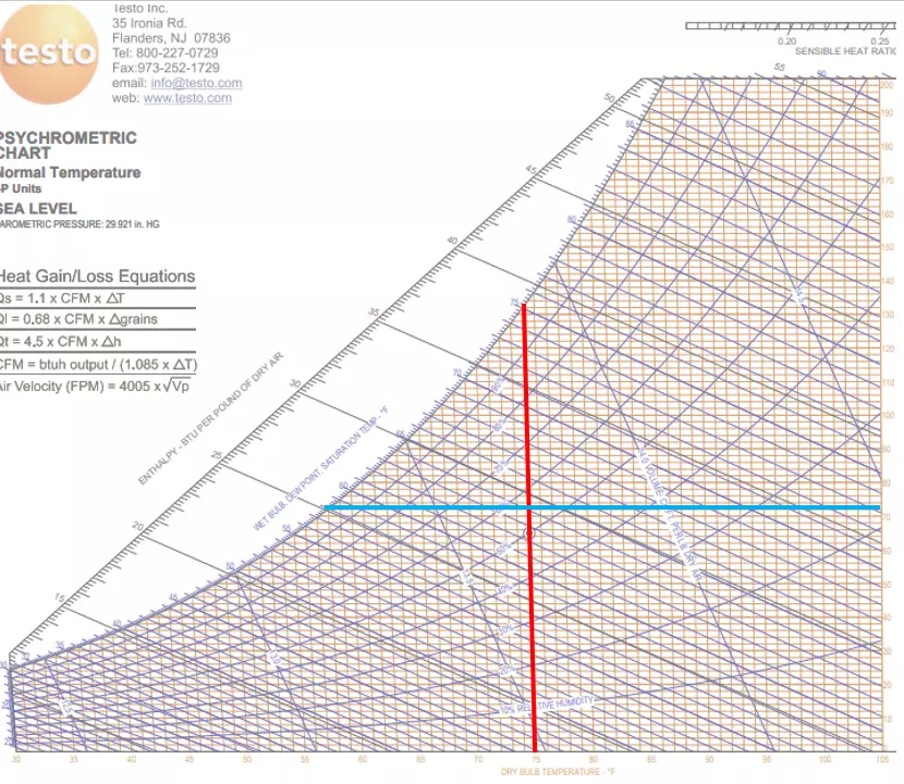Dry Bulb (red) and Dewpoint (blue) form a crosshair to indicate the current conditions of the air.
Let’s first understand what outdoor dew point tells us. The higher this number is, the more moisture is in the air. Humid climates like the Southern U.S. have extended periods of high dew point over 63F (17.C).
It’s not uncommon for coastal regions to experience periods of extremely high dew points of 80 (27C)!
Knowing what your outdoor dew point is can help you understand why condensation forms inside a duct, a wall, or another place where moisture droplets shouldn’t form. In fact, the ONLY place we want to see condensation form is on an evaporator coil. Anywhere else is undesirable.
Let’s say that your customer is noticing mildew in their home during humid weather. Biological growth forms as a result of condensation. You know that the outdoor dew point sometimes gets above 70F (21C), and humid air travels right through porous materials like wood and insulation.
If your customer likes to set the thermostat below 70, when the humid air hits a wall surface below its dew point temperature, condensation will form, leading to this growth. This can happen inside a wall where it can go unnoticed for a long time. Is the answer a dehumidifier?
A dehumidifier will help but only treats the symptoms, not the cause, by drying the *inside* of the building. The problem is high dew point air from *outside* is getting inside. The house needs to be air sealed. If it never had an effective water vapor barrier, such as house wrap, installed, this could be a major project.
As an HVAC technician, this is probably outside your scope of services. But understanding outdoor dew point will help you diagnose the problem correctly and point your customer in the right direction. It will also arm you with a scientific reason why your customer should not set their thermostat so low because it invites condensation to form.
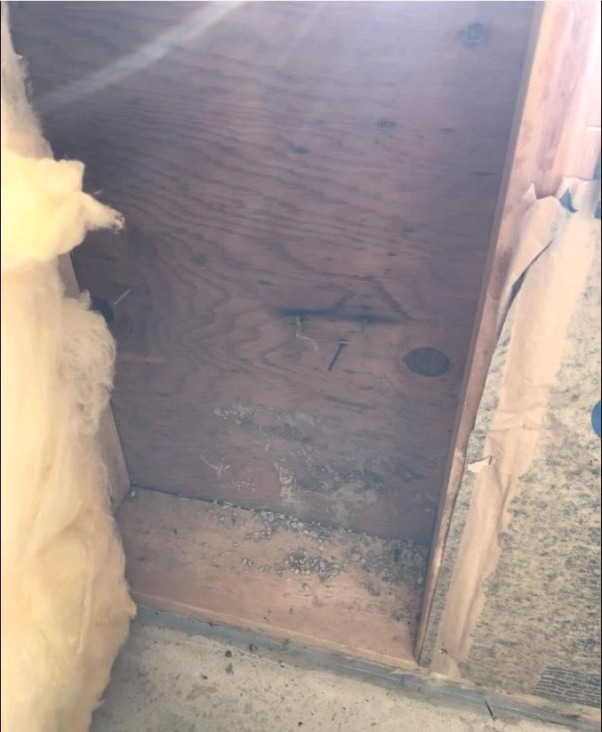Condensation in walls is caused by humid outside air leaking inside and can cause biological growth to form in the wall cavity.
Just like outdoor dew point that is above 63F (17C) is considered high, the same applies to indoor dew point. In fact, a few years ago, ASHRAE revised its [Standard 55](https://www.ashrae.org/technical-resources/bookstore/standard-55-thermal-environmental-conditions-for-human-occupancy) *Thermal Environmental Conditions for Human Comfort,* which now states that indoor dew point should not be higher than 62.2F (16.7C) to prevent mold. Prior to that, it only used relative humidity as a metric.
In Measurequick, you can change the Company Wide Settings “Air Moisture Indicators” from the default Wet bulb to the dew point. I suggest making this change if you have the authority to do so.
What can inside and return air dew point tell you? It will tell you how humid it is in the house.
If you are on a service call where the system is not running, you’ll probably find a high inside dew point, especially on a humid day with rain.Once the system is repaired, indoor dew point should return to normal.
But if you are on a maintenance, or a comfort consultation, taking an inside dew point measurement can identify a humidity problem that the occupant may not even be aware of. It will explain why there is condensation forming on the supply and even why mildew and biological growth are forming on surfaces around plumbing, duct, and electrical penetrations that are not sealed.
For the remainder of this article, I will go over various scenarios when checking dew point in 3 places:
1. Return Grille.
2. Return plenum
3. Supply Plenum.
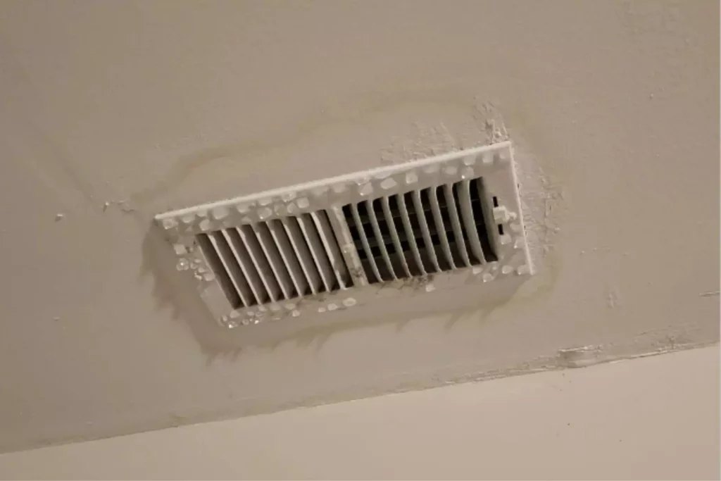Condensation forming on a supply register because of a high indoor dewpoint.
*The return grille* dew point and *return plenum* dew point are not always the same. And when they are drastically different, this is a huge red flag. In many places, the ducts run through unconditioned spaces like crawlspaces and attics, which generally have higher dew points.
Taking an initial indoor dew point reading at a return grille, you make find a normal dew point of 55F (13C).
Let’s say the return ducts run through an unconditioned attic to an air handler also in the attic. If you take a second dew point reading inside the return plenum at the air handler, you may find a much higher dew point, perhaps 65F (18C). That tells you that the return duct is picking up moisture!
Remember that dew point is an indicator of the *actual* moisture content in the air. How would a return duct pick up moisture? Through duct leakage! You may say: “I could’ve come to the same conclusion by measuring temperature instead of dew point.”
But if the ducts run through a very hot attic, the air is likely to pick up heat conducting through the walls of the duct, even if they are insulated, thus not proving there is leakage. Conversely, if the duct ran through a cool but humid crawlspace, you probably wouldn’t read a temperature rise (you might even read a temperature drop), but you definitely would see a dew point difference.
Remember, if fresh air is being introduced into the return plenum you would read a dew point difference at the return plenum. Understand that duct leakage is a huge source of indoor humidity problems.
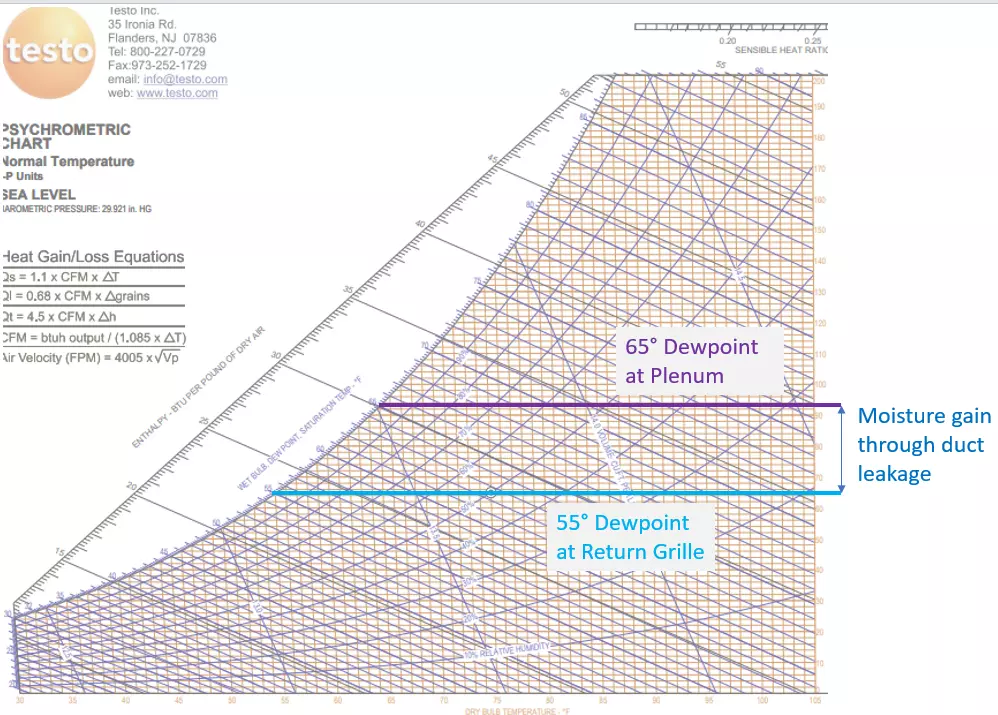Reading a vastly different Dewpoint between the return grille and the return plenum can indicate return duct leakage
I don’t often use the word “minutia,” but when I do, I often talk about things like supply air dew point. As warm air passes across the cold evaporator coil, the air molecules come into contact with the coil fins, and the moisture that the air contains starts falling out.
Theoretically, the air is “saturated” because it is cooled below its dew point. *When Dry Bulb and* dew point *temperatures are both the same the air is saturated.* In reality, not all the air comes into direct contact with the coil. Some of the air molecules pass through or around the coil unaffected.
This is called “coil bypass” – a condition where some air doesn’t make proper contact with the evaporator coil and therefore isn’t properly conditioned.
When that unaffected dry air then mixes back with the saturated air, the actual Dry Bulb might be 3-5 warmer than the dew point. The air is close to saturation but not quite saturated.
Let’s take an example with an air source heat pump in cooling mode. Reference the picture below.
If Supply Dry Bulb is 54F (12C) and the Supply dew point is 52F (11C) this tells us that the evaporator is cold and there is very little coil bypass. The air is close to saturation which is what we want. What if Supply is 59F (14C) but the supply air dew point is 52F (11C)?
What would cause such a large separation between Dry Bulb and dew point?
There may be a heat strip bank stuck on, reheating the air. Or there may be air bypassing the evaporator coil, mixing saturated air with unconditioned air. This can happen if the blower speed is set too high.
Sometimes the Supply air Dry bulb and dew point both read high while still being within a few degrees of each other. For example, Dry Bulb may be 58F (14C), and dew point is 56F (13C).
This usually indicates a high load on the evaporator, where coil temperature is higher than normal but leaving air is still close to saturation. The TXV is reacting to the high load. But measuring the dew point can alert a technician that there is a performance problem.
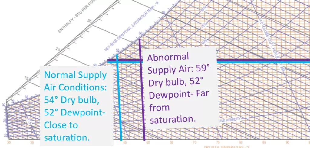Blue crosshair shows normal supply air conditions where the air is close to saturation. Purple crosshair shows an abnormal condition where the air is far from saturation.
The easiest way to get started is to get a pair of Bluetooth hygrometers that connect to Measurequick. Testo and Fieldpiece make some great products. Find a system cooling that is cooling properly and start a Non-Invasive test. Then, note the temperature and dew point at the return grille, return plenum, and supply plenum.
Think it through and be able to explain to yourself why you see these differences. Soon, you’ll get to the point where by taking the 3 dew point measurements alone, you’ll be able to quickly understand how the system is performing.
**Elevate Your Diagnostics with Property.com.** As a skilled HVAC technician mastering concepts like dew point, you know data is key. Property.com’s exclusive ‘[Know Before You Go](https://mccreadie.property.com)’ tool provides critical homeowner and property insights (permit history, home value, potential savings) before you even arrive. Complement your technical expertise with unparalleled property intelligence. Join our invitation-only network, boost your credibility with a Property.com subdomain, and access tools designed for top-tier pros. Limited spots available per region. Learn more about securing your exclusive advantage.
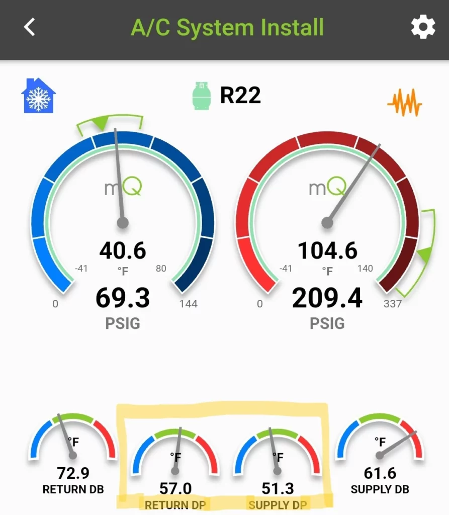Measurequick has the ability to display Return and Supply air Dewpoint [DP].
| Measurement | What It Measures | Why It Matters for HVAC |
| --- | --- | --- |
| **Dew Point** | Actual amount of moisture in the air; temperature at which condensation forms | Directly indicates moisture content regardless of temperature; best for diagnosing humidity problems |
| **Relative Humidity** | Percentage of maximum possible moisture at current temperature | Changes with temperature even when moisture content remains the same; less reliable for diagnostics |
| **Wet Bulb** | Temperature reading affected by evaporation; used to calculate enthalpy | Important for calculating cooling loads and system capacity; used with dry bulb for psychrometric calculations |
- **Outdoor dew point above 63F (17C)** indicates high humidity conditions that can lead to moisture problems
- **Indoor dew point should not exceed 62.2F (16.7C)** according to ASHRAE Standard 55 to prevent mold growth
- **Different dew points between return grille and return plenum** often indicate duct leakage or air infiltration issues
- **Supply air dew point and dry bulb temperatures** should be close (within 3-5F) in a properly functioning system
- **Measure dew point in three key locations:** return grille, return plenum, and supply plenum for comprehensive diagnosis
- **Modern tools** like Bluetooth hygrometers with app integration make dew point measurement quick and easy
## Conclusion
Checking systems using dew point is quick and easy once mastered. It is non-invasive and does not require the use of gauges or even pipe temperature clamps. But it is not a substitute for proper commissioning and benchmarking system performance. Think of it as a quick performance screening.
If you see something abnormal, investigate further. Understanding dewpoint is a key step to becoming a better technician. Be sure to use it and become the best practitioner you can be.
### Check out our discussion with Tim DeStasio on Building Comfort
document.addEventListener('DOMContentLoaded', function() {
var links = document.querySelectorAll('a[href="https://mccreadie.property.com"]');
links.forEach(function(link) {
link.addEventListener('click', function(event) {
if (typeof gtag === 'function') {
gtag('event', 'click', {
'event\_category': 'Outbound Link',
'event\_label': window.location.pathname,
'transport\_type': 'beacon'
});
}
});
});
});
{
"@context": "https://schema.org",
"@type": "TechArticle",
"headline": "Understanding Dew Point: The Essential Diagnostic Tool for HVAC Technicians",
"description": "Discover how dew point measurements can transform your HVAC diagnostic capabilities. Learn to identify humidity issues, duct leakage, and system performance problems with this practical guide.",
"image": "https://hvacknowitall.com/wp-content/uploads/2023/05/Testo-Psychrometric-chart.webp",
"author": {
"@type": "Person",
"name": "HVAC Know It All"
},
"publisher": {
"@type": "Organization",
"name": "HVAC Know It All",
"logo": {
"@type": "ImageObject",
"url": "https://hvacknowitall.com/wp-content/uploads/2022/11/HVAC-KIA-logo-1.png"
}
},
"datePublished": "2023-05-01",
"articleSection": "HVAC Diagnostics",
"mainEntityOfPage": {
"@type": "WebPage",
"@id": "https://hvacknowitall.com/blog/understanding-dew-point-to-be-a-better-hvac-technician"
},
"about": [
{
"@type": "Thing",
"name": "HVAC"
},
{
"@type": "Thing",
"name": "Dew Point"
},
{
"@type": "Thing",
"name": "Humidity Control"
}
]
}
--------------------------------------------------
# ID: 3319
## Title: The Three Fan Laws and Fan Curves Explained: A Complete HVAC Guide
## Type: blog_post
## Author: Tim De Stasio
## Publish Date: 2023-02-08T20:37:07
## Word Count: 2348
## Categories: None
## Tags: None
## Permalink: https://hvacknowitall.com/blog/the-3-fan-laws-and-fan-curve-charts
## Description:
# Understanding The Three Fan Laws and Fan Curve Charts in HVAC Systems
For HVAC professionals, understanding airflow dynamics and blower performance is essential for proper system design, equipment selection, and troubleshooting. These relationships are defined by three fundamental principles known as the fan laws.
These mathematical formulas describe how changes in fan speed affect airflow, static pressure, and power consumption. While system designers use these laws quantitatively when sizing equipment and ductwork, service technicians benefit from understanding them qualitativelyrecognizing how adjusting fan speed or addressing static pressure issues impacts system performance and efficiency.
This guide will explain each fan law in detail, demonstrate practical applications, and show you how to interpret fan curve charts for better equipment selection and system diagnostics.
## The Fundamental Laws of Fan Operation
### **Fan Law 1: CFM is directly proportional to RPM**
**Formula**: CFM = CFM (RPM RPM) or RPM = RPM (CFM CFM)
**What it means**: When you increase fan speed (RPM), airflow (CFM) increases at exactly the same ratea 1:1 ratio.
So if you need to increase CFM by 10%, your RPM has to increase by 10%.
Since this relationship is perfectly proportional, we can interchange RPM for CFM in Fan Laws 2 and 3 when needed.
We use Fan Law 1 all the time in the field. If we need to change airflow, we change fan speed either by changing a [motor speed tap](https://hvacknowitall.com/blog/how-hvac-motors-work), VFD output, pulley diameter, or other means.
**Apply it in the field**: If your blower is moving 1000 CFM at 1100 RPM, and you need to decrease airflow by 10% to 900 CFM, Fan Law 1 says your RPM must decrease by 10% also. Let’s put that in the formula:
RPM = RPM (CFM CFM)
RPM = 1100 (900 1000)
RPM = 990 This is your new RPM.
We also need to understand that for us to make predictions using this fan law and fan laws 2 and 3, everything else about the air and the system must stay the same, including air temperature and density. System friction must also stay constant, so these fan laws cannot be used with automatic dampers that self adjust to maintain flow.
### **Fan Law 2: Total Static Pressure changes with the square of CFM (or RPM)**
**Formula**: SP = SP (CFM CFM) or SP = SP (RPM RPM)
**What it means**: A modest increase in airflow creates a significant increase in static pressure. For example, a 10% increase in CFM will result in a 21% increase in Static Pressure.
Think about that.
A small increase in airflow creates a significant increase in duct pressure.
This increased pressure will be evenly distributed across components like coils and filters.
So this fan law can be applied to Total Static Pressure or a Static Pressure drop across a single component in the system.
That matters because some components have static pressure limitations that affect their performance.
Air filters work best when they have a low pressure drop across them, because this usually means the air velocity is low enough to allow for “dwell time” through the filter material, catching more particulates.
Condensate traps that are already close to their limit may have to be made deeper, so they don’t get overwhelmed.
Air proving switches must be adjusted so they do their job at the new CFM and Static Pressure.
**Apply it in the field:** At 1000 CFM, you read a 0.15w.c. pressure drop across a media filter.
You need to increase your airflow to 1200 CFM. What will be the new pressure drop?
SP = SP (CFM CFM)
SP = 0.15 (1200 1000)
SP = 0.26 w.c. This new pressure drop will probably be too high, according to most filter manufacturer specs that recommend less than 0.2. It will perform like a dirty filter, even when brand new.
The filter surface area now has to be increased.
Using Fan Law 2 to predict Static Pressure will prevent you from creating unintended consequences by increasing airflow on a system that is already close to its limit.
### **Fan Law 3: Horsepower changes with the cube of CFM (or RPM)**
**Formula**: HP = HP (CFM CFM) or HP = HP (RPM RPM)
**What it means**: Small changes in airflow or fan speed result in dramatic changes in motor power requirements. A 10% increase in airflow results in a 33% increase in horsepower required to do that work. If your [motor](https://hvacknowitall.com/blog/how-hvac-motors-work) is already close to its rated HP, a small airflow increase can overload it.
Let’s demonstrate that.
**Apply it in the field**: At 1000 CFM, your blower draws 1.5A.
You need to know how much HP it uses now and what your new HP will be when you increase airflow to 1200 CFM.
Use an [amps to hp conversion tool](https://www.inchcalculator.com/amps-to-horsepower-calculator/) to calculate HP in the Fan Law Formula.
You’ll have to know or make an educated guess what the motor efficiency and power factor is.
As you can see below, HP is 0.206 HP.
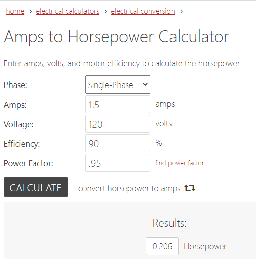
Now, what happens to HP when we increase the airflow from 1000 to 1200 CFM?
HP = HP (CFM CFM)
HP = 0.206 (1200 1000)
HP = 0.355. This is your new HP requirement.
What happens if your motor is only 1/3 HP (0.333)?
Your [motor](https://hvacknowitall.com/blog/troubleshooting-and-replacing-an-hvac-motor) will be overloaded and will not last long.
You’ll need to step up to a 1/2 HP motor.
Wouldn’t that be good to know *before* proposing the airflow change?
## **Fan Curve Charts Explained**
Manufacturers test their equipment under various conditions and document performance through “Fan Curve Charts.” These visual tools help predict how performance changes when variables like RPM and static pressure are adjusted.
Fan curve charts vary between manufacturers but typically appear as graphs like the one below. The curve represents performance at a constant RPM for a specific model.
To read the chart:
1. Draw a horizontal line from the Static Pressure axis to the curve
2. Draw a vertical line down to the CFM axis
3. The intersection point shows the airflow (CFM) at those conditions
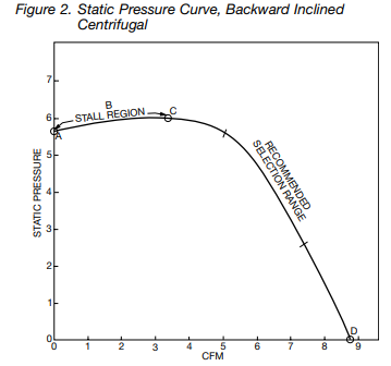
*Source: Twin City Fan*
Some manufacturers include a Brake Horsepower (BHP) curve to show power requirements at different operating conditions. The intersection of the fan curve and system curve defines the “Operating Point.” To determine required horsepower, draw a vertical line from the Operating Point up to the BHP curve.
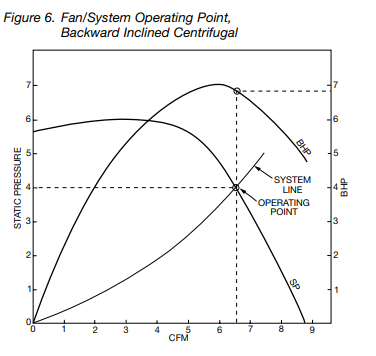
*Source: Twin City Fan*
## **Using the Three Fan Laws with Fan Curve Charts**
Manufacturers provide a “System Line” that represents the path a fan follows as conditions change. Any operating point must fall along this System Line.
Once you’ve identified an Operating Point on a fan curve chart at a known RPM, you can apply the three fan laws to predict performance changes when RPM or static pressure is adjusted.
**Example calculation:**
Referring to the fan curve above, assume:
– The curve represents 1000 RPM
– CFM units are x1000
– Static Pressure units are inches w.c.
– At the Operating Point, the fan delivers 6500 CFM at 4” w.c. with 6.9 BHP
If we want to reduce flow to 6000 CFM:
**What will the new RPM be?**
Fan Law 1: RPM = RPM (CFM CFM)
RPM = 1000 (6000 6500)
RPM = 923 RPM
**What will the new static pressure be?**
Fan Law 2: SP = SP (CFM CFM)
SP = 4 (6000 6500)
SP = 3.4” w.c.
**What will the new horsepower requirement be?**
Fan Law 3: HP = HP (CFM CFM)
HP = 6.9 (6000 6500)
HP = 5.4 HP
## **Selecting Equipment Using Fan Curve Charts**
Fan performance data is crucial for matching equipment to system requirements. In residential HVAC, we typically select air handlers based on tonnage calculations, then size ductwork to match the fan performance. In commercial applications, the process often reverseswe design the duct system first, then select a fan to overcome the calculated system resistance.
In either scenario, consulting manufacturer fan performance data ensures the selected equipment meets the specific needs of your system.
**Selection Example:** You need to select an exhaust fan for a commercial application requiring 1000 CFM at 0.5” w.c. static pressure. You’re comparing two Greenheck models: SQ-130-B and SQ-100-VG.
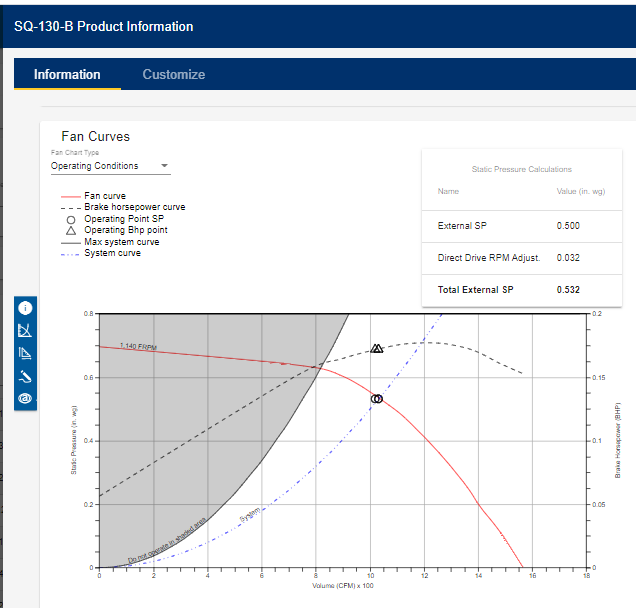 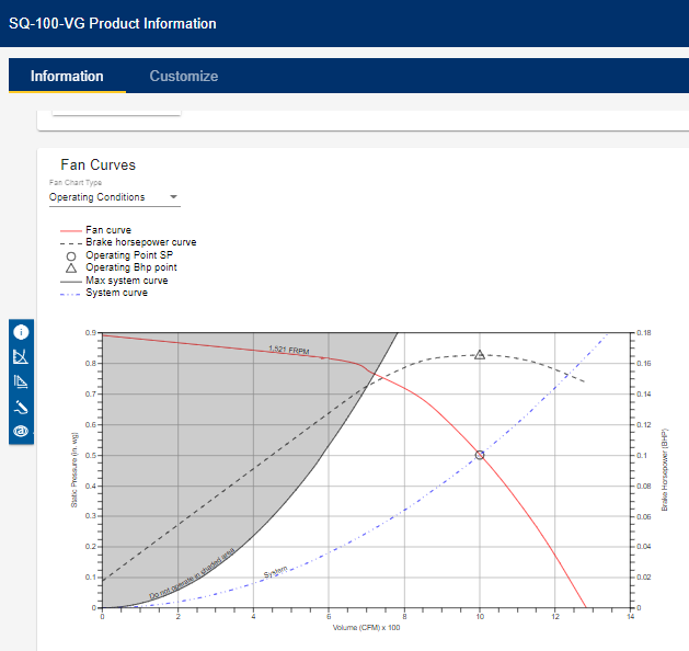
**Analysis:**
Both fans will satisfy the basic requirements, but they offer different advantages:
- The larger SQ-130-B operates at lower RPM (1140 vs. 1521), which typically means quieter operation and potentially longer bearing life.
- The smaller SQ-100-VG requires less brake horsepower, resulting in lower energy consumption and likely a lower initial purchase cost.
Your selection depends on project priorities. For noise-sensitive applications, choose the larger fan. For energy efficiency and lower initial cost, select the smaller model.
Note the shaded gray area on the charts, which indicates the “unstable region” where the fan operates too slowly for predictable performance. This phenomenon, called “stall and surge,” should be avoided for reliable operation.
Many manufacturers now offer selection software that automatically plots your design requirements on fan curve charts, but understanding how to read these charts manually remains an important skill for HVAC professionals.
## **Troubleshooting with Fan Laws**
Understanding fan laws provides valuable tools for diagnosing system issues. Here are common scenarios where applying these principles can help identify problems:
### **Low Airflow Issues**
If a system is delivering insufficient airflow:
1. **Measure current static pressure and compare to design specifications**
2. If static pressure is higher than expected, inspect for duct restrictions, dirty filters, or closed dampers (Fan Law 2 tells us higher resistance dramatically reduces airflow)
3. If static pressure is lower than expected, check for duct leakage or disconnected components
4. **Verify fan speed (RPM)**
5. Fan Law 1 tells us reduced RPM directly reduces airflow
6. Check belt tension, pulley alignment, or VFD settings
7. Confirm motor is operating at correct speed (not running on wrong voltage or experiencing bearing issues)
### **Motor Overloading**
If a motor is drawing excessive amperage or tripping overloads:
1. **Check if system modifications have occurred**
2. Fan Law 3 tells us small reductions in system resistance can cause significant increases in motor load
3. Added return air, removed filters, or opened dampers could reduce system static enough to overload the motor
4. **Verify fan speed hasn’t been increased**
5. Even modest increases in RPM can dramatically increase power requirements
6. Check for pulley or sheave replacements that may have altered fan speed
### **Noise and Vibration**
Excessive noise often indicates the fan is operating outside its intended range:
1. **Check operating point on fan curve**
2. Operating too far left on the curve (high static, low flow) can cause stall conditions
3. Operating too far right (low static, high flow) can overload the motor and increase turbulence
4. **Apply Fan Law 1 to reduce speed**
5. Slight speed reductions can significantly reduce noise while maintaining acceptable performance
Remember that changes to address one issue will impact other aspects of system performance. Always apply all three fan laws to predict the full range of effects before making adjustments.
## **HVAC Airflow Terminology Glossary**
- **CFM (Cubic Feet per Minute)**: Measure of airflow volume; the amount of air moving through a system.
- **RPM (Revolutions Per Minute)**: The rotational speed of a fan or blower wheel.
- **SP (Static Pressure)**: The resistance to airflow in a duct system, measured in inches of water column (w.c.).
- **BHP (Brake Horsepower)**: The actual power required to drive a fan, not including motor efficiency losses.
- **w.c. (Water Column)**: A unit of pressure measurement commonly used in HVAC; 1” w.c. equals 0.036 psi.
- **Operating Point**: The intersection of the fan curve and system curve, representing the actual performance point.
- **System Curve**: A graphical representation of how system resistance changes with airflow.
- **Fan Curve**: A graphical representation of fan performance at a specific RPM.
- **Stall**: Condition where airflow separates from the fan blade, causing unstable operation and increased noise.
## Conclusion: Mastering Fan Laws for Better HVAC Service
Understanding the three fan laws enables HVAC professionals to make precise airflow adjustments and predict system changes before implementation. Commercial technicians who commission and balance equipment should be particularly familiar with fan curve charts to eliminate guesswork and identify potential design issues.
Even for residential service technicians, this knowledge provides a foundation for more effective troubleshooting and system optimization. By applying these principles, you’ll make more informed decisions, avoid unintended consequences when modifying systems, and ultimately deliver better service to your customers.
Mastering fan laws sets you apart. Ready to leverage that expertise? [Property.com](https://mccreadie.property.com) offers top HVAC Pros an exclusive platform to boost credibility with a custom subdomain, manage reputation with AI tools, and connect with premium clients. Limited spots available per region. Become a Property.com Certified Pro and secure your advantage.
*Originally Published on [Tim De Stasio HVAC](https://timdestasiohvac.wordpress.com/2022/10/14/the-3-fan-laws-and-fan-curve-charts/)*
document.addEventListener('DOMContentLoaded', function() {
var links = document.querySelectorAll('a[href="https://mccreadie.property.com"]');
links.forEach(function(link) {
link.addEventListener('click', function(event) {
if (typeof gtag === 'function') {
gtag('event', 'click', {
'event\_category': 'Outbound Link',
'event\_label': window.location.pathname,
'transport\_type': 'beacon'
});
}
});
});
});
{
"@context": "https://schema.org",
"@type": "TechArticle",
"headline": "The Three Fan Laws and Fan Curves Explained: A Complete HVAC Guide",
"description": "Master the three fan laws in HVAC systems to understand relationships between fan speed, airflow, pressure, and power. Learn how to read fan curves for proper equipment selection and troubleshooting.",
"author": {
"@type": "Person",
"name": "Tim De Stasio"
},
"publisher": {
"@type": "Organization",
"name": "HVAC Know It All",
"logo": {
"@type": "ImageObject",
"url": "https://hvacknowitall.com/wp-content/uploads/2022/05/HVAC-Know-It-All-Horizontal-Copy.png"
}
},
"datePublished": "2023-02-01",
"image": "https://hvacknowitall.com/wp-content/uploads/2023/02/Fan-system-operating-point.webp",
"mainEntityOfPage": {
"@type": "WebPage",
"@id": "https://hvacknowitall.com/blog/the-3-fan-laws-and-fan-curve-charts"
},
"about": [
{
"@type": "DefinedTerm",
"name": "CFM",
"description": "Cubic Feet per Minute - measure of airflow volume in HVAC systems"
},
{
"@type": "DefinedTerm",
"name": "RPM",
"description": "Revolutions Per Minute - speed of fan rotation"
},
{
"@type": "DefinedTerm",
"name": "Static Pressure",
"description": "Resistance to airflow in an HVAC system, measured in inches water column (w.c.)"
},
{
"@type": "DefinedTerm",
"name": "Brake Horsepower",
"description": "Actual power required to drive a fan, not including motor efficiency losses"
}
],
"knowsAbout": [
"HVAC",
"Fan Laws",
"Fan Curves",
"Airflow",
"Equipment Selection"
]
}
--------------------------------------------------
# ID: 16
## Title: HVAC Troubleshooting: A Comprehensive Guide for Technicians
## Type: blog_post
## Author: Gary McCreadie
## Publish Date: 2022-10-30T16:54:31
## Word Count: 2502
## Categories: Troubleshooting
## Tags: Commercial HVAC, customer communication, electrical testing, equipment repair, Featured, HVAC maintenance, HVAC troubleshooting, manifold gauges, mechanical systems, multimeter testing, preventive maintenance, refrigeration systems, safety protocols, service technician, system performance, technical support
## Permalink: https://hvacknowitall.com/blog/general-guide-to-hvac-troubleshooting
## Description:
## Master the Art of HVAC Troubleshooting
**This comprehensive guide serves as an essential roadmap for HVAC technicians at any experience level:**
- Learn to think like a skilled trades detective
- Understand which diagnostic tools provide the clearest system insights
- Master the sequence of operations and wiring diagram interpretation
- Follow a proven step-by-step approach to service calls that leads to verified solutions
This guide focuses on the fundamental troubleshooting methodology that applies across HVAC systems. We won’t delve into specifics involving local codes, manufacturer procedures, or advanced analyses like static pressure, superheat, or subcooling. For those topics, see our detailed guide on [Walk-In Cooler Troubleshooting](https://hvacknowitall.com/blog/walk-in-cooler-troubleshooting).
Before proceeding, understand that effective troubleshooting requires solid knowledge of basic refrigeration principles, heating fundamentals, and electrical concepts. This foundation is essential for safe and accurate diagnosis.
New to the field? Consider consulting with senior technicians during service calls or joining the HVAC Know It All [community](https://bluecollarguru.disciplemedia.com/signup) for ongoing professional support.
This article outlines the critical checkpoints every technician must navigate before proceeding to system-specific diagnosis and repair.
\*\* PRO TIP:\*\* Before beginning any troubleshooting, ensure you have appropriate PPE (personal protective equipment) including safety glasses and gloves.
This article is complemented by a podcast episode discussing HVAC/R service. Listen on the [HVAC Know It All Podcast](https://anchor.fm/hvacknowitall/episodes/A-General-Guide-To-HVACR-Troubleshooting-en165r)
[](https://anchor.fm/hvacknowitall/episodes/A-General-Guide-To-HVACR-Troubleshooting-en165r)
Effective diagnosis requires the right tools. The following equipment will help you build a comprehensive picture of system issues and identify solutions efficiently.
### Manifold Gauges
Manifold gauges measure system pressures in air conditioning and refrigeration systems while indicating saturated temperatures for specific refrigerants.
If your gauge doesn’t include a scale for your working refrigerant, keep a pressure/temperature chart on hand for reference.
Digital manifold options include both traditional sets and [smart probes from Testo](https://www.testo.com). These digital tools incorporate pressure/temperature calculations automatically, displaying results on-screen or through mobile applications.
This video demonstrates checking evaporator superheat using smart probes:
### Temperature Probe or Clamp
Temperature sensing devices that mount on refrigerant lines are essential for checking superheat and subcooling measurementscritical indicators of system performance.
### Multimeter
A quality multimeter is perhaps your most frequently used diagnostic tool, as many HVAC problems stem from electrical issues.
Your multimeter or combination of meters should measure:
\* AC/DC voltage
\* Amperage draw
\* Resistance (Ohms)
\* Capacitor microfarads
\* DC microamps (for flame sensor testing)
Watch these videos for practical demonstrations of multimeter applications:
\* [Testing flame signal using DC microamps](https://youtu.be/gV7vjjtpJ5c)
\* [Troubleshooting a walk-in cooler condensing unit](https://youtu.be/cfUUr0J8q3w)
### Dual Port Manometer
Manometers serve multiple diagnostic functions:
\* Checking gas pressure in heating appliances
\* Measuring differential pressure across coils and filters
\* Evaluating static pressure in duct systems
Modern manometers offer digital displays or Bluetooth connectivity to mobile devices for enhanced functionality and data recording.
For field applications, see these demonstration videos:
\* [Standard manometer in use](https://youtu.be/tsLgkRaEyBY)
\* [Bluetooth manometer demonstration](https://youtu.be/a5SR4Ys6Fsk)
### Electronic Refrigerant Leak Detector
Quality electronic leak detectors allow rapid identification of refrigerant leaks. For best results, use both electronic detection and soap solution for verification.
For detailed leak checking protocols, follow our [Refrigerant Leak Checking Procedure](https://hvacknowitall.com/blog/refrigerant-leak-checking-procedure).
### Hygrometer
Hygrometers measure temperature and humidity, providing critical data points including wet bulb temperature and [dew point](https://hvacknowitall.com/blog/understanding-dew-point).
These measurements are valuable for comparing:
\* Outdoor versus indoor conditions
\* Supply air versus return air parameters
\* Room condition assessments
### Additional Diagnostic Tools
Other specialized instruments that enhance troubleshooting capabilities include:
\* Combustion analyzer
\* Infrared temperature gun
\* Thermal imager
\* Rotating vane or hot wire anemometer
Before starting any troubleshooting process, you must understand the equipment’s sequence of operationswhat happens first, second, and so on. This knowledge forms the foundation for logical diagnosis.
For example, a typical residential furnace follows this sequence:
1. Thermostat initiates a call for heat
2. Induced draft motor starts and air flow is verified by the pressure switch
3. Pre-purge cycle clears the combustion chamber and venting
4. Ignition control activates after confirming all safety switches are closed
5. Ignition source (spark or hot surface ignitor) energizes and gas valve opens
6. Burner ignites and flame is verified by sensor
7. After a delay to allow heat exchanger warming, the blower fan starts
8. When thermostat is satisfied, gas valve closes and burner shuts down
9. Induced fan performs post-purge cycle
10. Blower continues running to cool down the heat exchanger
Watch this video walkthrough of troubleshooting a no-heat call:
\*\* PRO TIP:\*\* Understanding wiring diagrams is essential for effective troubleshooting and comprehending sequence of operations. Developing expertise in reading these diagrams will significantly improve your diagnostic accuracy and safety.
> [View this post on Instagram](https://www.instagram.com/p/CIQy4qarD0J/?utm_source=ig_embed&utm_campaign=loading)
>
> [A post shared by Gary McCreadie HVAC/R Tech/Business Owner (@hvacknowitall1)](https://www.instagram.com/p/CIQy4qarD0J/?utm_source=ig_embed&utm_campaign=loading)
Different equipment types will follow their own specific sequences. For complex systems, refer to our guide on [Commercial System Upgrades](https://hvacknowitall.com/blog/hvac-retrofits-a-guide-to-commercial-system-upgrades).
Always consult manufacturer documentation and technical support when working with unfamiliar equipment.
Successful troubleshooting requires a methodical approach. Follow these steps in sequence to ensure thorough diagnosis and effective problem-solving.
### Step One: Customer Communication
Effective customer interaction provides valuable diagnostic information:
- Contact the customer before arrival when possible
- Ask them to describe the issue in detail
- Request photos or videos of the equipment (from a safe distance)
- Gather information about when and how the problem occurs
\*\* SAFETY NOTE:\*\* Never ask customers to remove panels, reset controls, or perform any potentially hazardous actions.
\*\* PRO TIP:\*\* You can [‘train’ your customer](https://hvacknowitall.com/blog/train-your-customer) through clear communication about boundaries and expectations.
Avoid pre-diagnosing based on the customer’s description alone. While en route, keep an open mind rather than fixating on a specific diagnosis. This prevents confirmation bias that might cause you to overlook the actual problem.
Upon arrival, gather additional information:
\* Duration of the issue
\* Frequency of occurrence
\* Specific conditions when the problem appears
\* Any changes made to the system recently
If available, review trend logs showing ambient conditions or system performance.
\*\* PRO TIP:\*\* While customer input is valuable, remember that you are the professional. Never simply accept a customer’s diagnosis without verification.
### Step Two: Inspect Using Your Senses
**SAFETY FIRST:** When entering enclosed spaces with fuel-burning equipment, wear a personal carbon monoxide monitor for your protection.
Begin with a thorough visual inspection before using diagnostic tools:
- Look for obvious issues:
- Dirty or damaged components
- Loose or disconnected wiring
- Improper venting
- Signs of water damage or corrosion
- Unusual component positioning
Engage all your senses:
\* **Listening:** Identify unusual noises (grinding, buzzing, rattling)
\* **Smelling:** Detect burnt components, fuel odors, or refrigerant leaks
\* **Touching:** Feel for excessive vibration or temperature abnormalities (after confirming power is off)
Temperature reference: Your palm is approximately 92F (33C). Components feeling warmer than your hand exceed this temperature.
\*\* PRO TIP:\*\* Always disconnect and verify power is off before reaching into equipment cabinets. Use lock-out/tag-out procedures when appropriate.

### Step Three: Verifying Power
After initial inspection, verify all power sources:
1. **Primary Power:** Confirm the correct voltage is reaching the equipment
2. If power is absent, check for tripped breakers or blown fuses
3. If breakers are tripped, investigate potential shorts in wiring or primary loads
4. **Control/Secondary Power:** Verify appropriate control voltage
5. Usually 24V in residential systems
6. Typically supplied by a step-down transformer
\*\* PRO TIP:\*\* When dealing with primary power issues, disconnect the “R” wire from the low voltage terminal strip during troubleshooting to prevent equipment from trying to operate.
1. **Control System:** Ensure thermostats or building automation systems are:
2. Properly powered
3. Functioning correctly
4. Programmed appropriately
\*\* PRO TIP:\*\* To diagnose a potentially faulty thermostat, bypass it by jumping terminals at the sub-base (e.g., connecting R to Y1 for cooling). If equipment starts, the thermostat may be defective.
### Step Four: Heat Exchange Medium
Proper heat exchange requires appropriate medium flow:
- For air systems: Verify correct airflow
- For hydronic systems: Confirm proper fluid flow
Check that:
\* Fans or pumps are powered and running in the correct direction
\* Air filters or fluid strainers are clean and unobstructed
\* System is properly balanced
Until proper flow is confirmed, avoid running heating or cooling functions.
\*\* PRO TIP:\*\* If a fan or pump fails to start, check:
\* Incoming power
\* Capacitors (if applicable)
\* Relays and contactors
\* Control board input/output signals
\*\* PRO TIP:\*\* For systems with control boards, verify both input and output signals. If the board receives proper input but produces no output under normal circumstances, the board is likely defective.
### Step Five: Full System Diagnosis
After completing the previous steps, proceed to full system diagnosis.
For a cooling system where the compressor/condenser fan contactor fails to engage:
\* Check safety circuits for open switches (high/low pressure switches)
\* Verify interlock circuits are functioning
\* Test contactor coil for proper voltage and operation
\* Look for broken common connections in the control circuit
If the contactor engages but components don’t start:
\* Verify correct voltage through the contactor to each load
\* Check capacitors and start components
\* Test motor windings for continuity
\*\* PRO TIP:\*\* For single-phase systems, check voltage across compressor C (common) and R (run) terminals. For three-phase systems, check across all phase combinations: T1-T2, T1-T3, and T2-T3.
When components start but performance issues persist:
\* Measure amperage draw of each component against nameplate specifications
\* Evaluate system performance parameters:
\* Saturated condensing temperature
\* Saturated suction temperature
\* Superheat and subcooling
\* Compare readings to manufacturer specifications
\*\* PRO TIP:\*\* Digital tools like [Testo Smart Probes](https://www.testo.com/en-US/products/smart-probes) paired with apps like [measureQuick](https://measurequick.com/) can streamline diagnosis by calculating target values and performance metrics automatically.
Remember that verification is essential. Assumptions without testing lead to incorrect diagnoses and unnecessary parts replacements.
**Become the Ultimate HVAC Detective.** Arrive prepared for every service call with Property.com’s exclusive ‘[Know Before You Go](https://mccreadie.property.com)’ tool. Access homeowner permit history, home value, and potential upgrade savings instantly. Elevate your diagnostics and stand out with Property.com certification. Limited spots available per region secure your exclusive advantage today.
Even experienced technicians can fall into diagnostic traps. Avoid these common troubleshooting pitfalls:
### Jumping to Conclusions
Perhaps the most prevalent mistake is assuming you know the problem before completing a thorough diagnosis. This often results in:
\* Replacing parts unnecessarily
\* Missing the actual underlying issue
\* Wasting time and resources
\* Damaging your professional reputation
**Solution:** Follow the systematic approach outlined in this guide every time, regardless of how “obvious” the problem may seem.
### Overlooking the Basics
When facing complex issues, technicians sometimes skip fundamental checks:
\* Not verifying proper voltage
\* Failing to check for loose connections
\* Ignoring thermostat settings or programming
\* Neglecting to inspect filters and airflow
**Solution:** Always start with the fundamentals before moving to advanced diagnostics.
### Misinterpreting Symptoms
Similar symptoms can have different causes:
\* Low pressure readings could indicate refrigerant leak OR restricted airflow
\* No cooling might be a refrigerant issue OR a control problem
\* System short-cycling could be caused by oversizing OR faulty controls
**Solution:** Consider all possible causes for each symptom and test systematically to eliminate possibilities.
### Poor Documentation
Failing to document findings properly leads to:
\* Difficulty tracking intermittent issues
\* Inability to establish performance baselines
\* Challenges communicating with customers or other technicians
**Solution:** Keep detailed records of all readings, observations, and repairs for future reference.
### Neglecting Safety Protocols
Safety shortcuts not only risk personal injury but also compromise diagnostic accuracy:
\* Working on live circuits leads to inaccurate readings
\* Skipping PPE increases accident risks
\* Rushing through safety checks endangers you and the customer
**Solution:** Never compromise on safety procedures, regardless of time pressures.
## In Summary: The HVAC Detective’s Approach
Effective HVAC troubleshooting combines technical knowledge, systematic methodology, and attention to detail. To recap the essential elements:
- Approach each service call as a skilled trades detective, gathering evidence methodically
- Use the right diagnostic tools to collect accurate system data
- Master equipment sequence of operations and wiring diagrams
- Follow the step-by-step troubleshooting approach:
- Communicate effectively with customers
- Use all senses during initial inspection
- Verify proper power at all levels
- Ensure correct heat exchange medium flow
- Complete a thorough system diagnosis
- Always verify your diagnosis before concluding
Remember that some issues resolve quickly, while others require extended investigation. The complexity of modern HVAC systems demands patience and persistence.
For aspiring HVAC technicians or those early in their careers, this video offers valuable motivation and perspective:
For more detailed troubleshooting guides on specific components and systems, explore our technical resource library:
- [Checking Run Capacitors Under Load](https://hvacknowitall.com/blog/checking-run-capacitors-under-load)
- [Understanding PCB Components](https://hvacknowitall.com/blog/guide-to-hvac-pcb-components)
- [Walk-In Cooler Troubleshooting Guide](https://hvacknowitall.com/blog/walk-in-cooler-troubleshooting)
**Good luck and happy troubleshooting!**
document.addEventListener('DOMContentLoaded', function() {
var links = document.querySelectorAll('a[href="https://mccreadie.property.com"]');
links.forEach(function(link) {
link.addEventListener('click', function(event) {
if (typeof gtag === 'function') {
gtag('event', 'click', {
'event\_category': 'Outbound Link',
'event\_label': window.location.pathname,
'transport\_type': 'beacon'
});
}
});
});
});
{
"@context": "https://schema.org",
"@type": "FAQPage",
"mainEntity": [
{
"@type": "Question",
"name": "What essential diagnostic tools are needed for HVAC troubleshooting?",
"acceptedAnswer": {
"@type": "Answer",
"text": "Essential diagnostic tools include manifold gauges, temperature probes, multimeters, dual port manometers, electronic refrigerant leak detectors, and hygrometers. Additional specialized tools include combustion analyzers, infrared temperature guns, thermal imagers, and anemometers."
}
},
{
"@type": "Question",
"name": "Why is understanding sequence of operations important for HVAC troubleshooting?",
"acceptedAnswer": {
"@type": "Answer",
"text": "Understanding sequence of operations is essential because it shows what happens first, second, and so on in an HVAC system's functioning. This knowledge forms the foundation for logical diagnosis by helping technicians identify which step in the sequence is failing."
}
},
{
"@type": "Question",
"name": "What are the five systematic steps to HVAC troubleshooting?",
"acceptedAnswer": {
"@type": "Answer",
"text": "The five systematic steps are: 1) Customer Communication - gathering information about the issue, 2) Inspection Using Your Senses - visual and sensory evaluation, 3) Verifying Power - checking primary and secondary power sources, 4) Heat Exchange Medium - ensuring proper airflow or fluid flow, and 5) Full System Diagnosis - comprehensive testing of system components and performance."
}
},
{
"@type": "Question",
"name": "How should technicians approach customer communication during troubleshooting?",
"acceptedAnswer": {
"@type": "Answer",
"text": "Technicians should contact customers before arrival when possible, ask them to describe the issue in detail, and request photos or videos of the equipment (from a safe distance). They should gather information about when and how the problem occurs without accepting the customer's diagnosis as fact. Clear communication about boundaries and expectations is important."
}
},
{
"@type": "Question",
"name": "What common mistakes should HVAC technicians avoid when troubleshooting?",
"acceptedAnswer": {
"@type": "Answer",
"text": "Common mistakes include jumping to conclusions without proper diagnosis, overlooking basic checks, misinterpreting symptoms, poor documentation of findings, and neglecting safety protocols. Following a systematic approach and verifying all diagnoses can help avoid these pitfalls."
}
}
]
}
--------------------------------------------------
# ID: 3385
## Title: Brazing Alternatives for HVACR Technicians: Modern Solutions for Today’s Challenges
## Type: blog_post
## Author: Gary McCreadie
## Publish Date: 2022-09-21T08:00:01
## Word Count: 1917
## Categories: Education
## Tags: None
## Permalink: https://hvacknowitall.com/blog/brazing-alternatives
## Description:
## Brazing Alternatives for the Progressive HVACR Technician
Mention “brazing alternatives” to hardcore HVACR professionals, and you might get those mad face emojis in response! Understandably so – brazing provides a solid, proven connection that lasts for many years and remains a fundamental skill for all HVACR professionals.
While I don’t subscribe to the notion that “brazing is an art” (art is unique expression, while brazing should be a repeatable process with consistent results), I certainly respect its importance in our industry. Contrary to what some might think, I’m not anti-brazing – I simply enjoy exploring new technologies that can enhance our HVACR toolkit.
In this article, we’ll examine four proven brazing alternatives that every progressive technician should know about:
1. Pro Fit Quick Connect – Push-to-connect fittings for quick repairs
2. AC Smart Seal External – Leak sealant for inaccessible or difficult areas
3. FixQuick – Two-part repair system for specialized applications
4. Rapid Locking System – Press-to-connect system for comprehensive installations
I’ve personally tested these alternatives and will share my experience with each, including when and why you might choose them over traditional brazing methods. I’ve been particularly impressed with the [SolderWeld](https://solderweld.us/) products lately and how well the rods flow.
> [View this post on Instagram](https://www.instagram.com/p/CdenpUSLu2l/?utm_source=ig_embed&utm_campaign=loading)
>
> [A post shared by Gary McCreadie HVAC/R Tech/Business Owner (@hvacknowitall1)](https://www.instagram.com/p/CdenpUSLu2l/?utm_source=ig_embed&utm_campaign=loading)
There are several compelling reasons why brazing alternatives continue to be developed and adopted in our industry:
### Fire Safety Concerns
Fire hazards represent one of the most compelling reasons to explore brazing alternatives. I once worked in a facility that required a 4-hour fire watch after torch use – a time-consuming requirement in today’s fast-paced service environment. The building’s wooden beam construction made this precaution necessary but created significant workflow challenges.
“Hot work” fires occur more frequently than many realize. According to the National Fire Protection Association, [an average of 4,630 structure fires involving hot work occur each year](https://www.nfpa.org/-/media/Files/Code-or-topic-fact-sheets/HotWorkFactSheet.pdf), causing significant property damage and putting lives at risk.
As these statistics become better known, more building managers are implementing stricter rules around torch use, making brazing alternatives increasingly necessary for HVACR professionals.
### Health and Environmental Considerations
Brazing fumes contain numerous potentially harmful substances, particularly when working in poorly ventilated areas. My experience in data centers highlights this issue – these sealed environments maintain precise temperature and humidity levels, meaning fumes can linger for hours, affecting everyone in the space.
The University of Alabama’s [comprehensive guide on welding, cutting, and brazing safety](https://ehs.ua.edu/operations/occupational-safety/shop-safety/welding-cutting-brazing/) details the health risks associated with these processes.
### Specialized Environment Restrictions
Certain settings – medical facilities, pharmaceutical manufacturing plants, clean rooms, and other sensitive environments – may prohibit open flames entirely. In these locations, non-brazing alternatives aren’t just convenient; they’re mandatory.
This video provides additional perspective on when alternatives might be preferable:
RectorSeal’s [PRO-Fit Quick Connect](https://rectorseal.com/quickconnect-lp) offers a flame-free connection method that’s gaining popularity among service technicians. While my experience at the time of writing is limited to bench testing, numerous colleagues have reported excellent results in field applications.
These push-to-connect fittings excel in challenging service scenarios where:
– Torch access is difficult (cramped attics, tight crawl spaces)
– Fire permits would cause excessive delays
– The environment prohibits open flames
– Equipment or surroundings could be damaged by heat
### Installation Considerations
As with any pipe fitting method, proper preparation is crucial:
1. Thoroughly clean the pipe to remove any debris or contaminants
2. Use the included depth gauge to mark insertion depth on the pipe
3. Ensure the pipe end is properly deburred and has no sharp edges
4. Insert the pipe to the marked depth with a slight twisting motion
The PRO-Fit system particularly shines in emergency repair situations where minimizing system downtime is critical, such as in server rooms or other climate-controlled environments where temperature excursions could damage sensitive equipment.
> [View this post on Instagram](https://www.instagram.com/reel/ChlMkctPjcC/?utm_source=ig_embed&utm_campaign=loading)
>
> [A post shared by Gary McCreadie HVAC/R Tech/Business Owner (@hvacknowitall1)](https://www.instagram.com/reel/ChlMkctPjcC/?utm_source=ig_embed&utm_campaign=loading)
[AC Smart Seal External](https://www.coolairproducts.net/ac-smart-seal-external/) provides an innovative solution for addressing small external refrigerant leaks without brazing. This product has proven particularly valuable in my own service work.
My first real-world application was in a data center environment where a rub-through on a capillary line had caused a water regulator valve to lose its refrigerant charge. The environment presented multiple challenges:
– Restricted access for bringing in torch equipment
– Fire permit requirements that would delay repairs
– Poor ventilation that would trap brazing fumes
– Sensitive electronic equipment vulnerable to fire hazards
The application process is straightforward:
1. Clean and dry the leak area thoroughly
2. Apply the putty-like substance directly over the leak
3. Allow proper curing time according to manufacturer specifications
4. Pressure test the system to verify the seal
5. Evacuate the system per standard procedures
In my case, the repair maintained system integrity for a full year until the valve could be completely replaced during scheduled maintenance. This example perfectly illustrates when an alternative to brazing isn’t just convenientit’s the superior technical solution.
For more details on proper system testing after repairs, see our guide on [pressure testing refrigeration systems](https://hvacknowitall.com/blog/pressure-testing-refrigeration-systems).
[FixQuick](https://www.coolairproducts.net/fixquick/) presents another innovative approach to leak repair without flames. In my bench testing, this system successfully maintained pressures up to approximately 400 PSIimpressive performance that suggests real-world reliability.
### How FixQuick Works
This two-component system consists of:
1. A specialized liquid base
2. A powder accelerant that triggers the hardening process
The chemical reaction between these components creates a durable seal capable of withstanding significant system pressures.
### Ideal Applications
FixQuick is particularly well-suited for:
– Evaporator repairs where corrosion has weakened the metal, making heat-based repairs risky
– Areas with restricted access where torch use would be challenging
– Emergency repairs when minimizing downtime is critical
– Locations where fire permits would cause significant delays
The product’s unique formulation gives it excellent adhesion properties even under challenging conditions, including the presence of oils and some contaminants (though proper cleaning is always recommended).
See FixQuick in action in this demonstration video:
The [Rapid Locking System (RLS)](https://www.rapidlockingsystem.com/) represents perhaps the most comprehensive brazing alternative for HVACR applications. This press-to-connect technology offers a complete solution for both repairs and full installations.
### System Components
RLS provides a comprehensive selection of:
– Line fittings in various configurations
– Valves for system control
– Filter driers for contaminant removal
– Sight glass assemblies for system monitoring
This diversity makes it possible to complete entire refrigeration projects without lighting a single torch.
### Personal Experience
While I haven’t personally completed full installation projects with RLS, I’ve successfully:
– Performed numerous system repairs
– Replaced filter driers in existing systems
– Completed unfinished installation projects started by others
Each experience reinforced my confidence in the technology. The press connection process requires an initial investment in tools but delivers consistent, reliable results when proper procedures are followed.
### Learning Curve Considerations
RLS does represent a departure from traditional techniques, requiring:
1. Proper training in the pressing process
2. Understanding of the system’s specific preparation requirements
3. Familiarity with the specialized tools
4. Recognition of appropriate applications
The manufacturer provides extensive training resources to help technicians master these aspects. I strongly recommend reaching out to RLS directly if you’re interested in implementing this technology into your service offerings.
For a visual demonstration of the RLS system, check out this informative video:
When selecting from these brazing alternatives, consider the specific requirements of your job. This comparison table highlights key characteristics of each option:
| Alternative | Initial Cost | Application Type | Learning Curve | Pressure Rating | Best Used For |
| --- | --- | --- | --- | --- | --- |
| Pro Fit Quick Connect | Low-Medium | Repair/Limited Installs | Low | High | Emergency repairs, difficult access areas |
| AC Smart Seal External | Low | Repair Only | Very Low | Medium-High | Small pinhole leaks, emergency repairs |
| FixQuick | Low | Repair Only | Low | High | Corrosion-damaged components, emergency repairs |
| Rapid Locking System | High | Comprehensive Install/Repair | Medium | Very High | Complete installations, system retrofits |
### Cost Considerations
While some alternatives require a higher initial investment (especially RLS with its specialized tools), consider the long-term savings from:
– Reduced labor time on complex installations
– Eliminated fire permit requirements
– Lower insurance costs from reduced fire risk
– Expanded service capabilities in restricted environments
### Safety Advantages
All these alternatives share significant safety benefits:
– Elimination of fire hazards
– Reduced technician exposure to brazing fumes
– Decreased risk of thermal damage to sensitive components
– Lower liability risk in sensitive environments
### When to Stick with Brazing
Traditional brazing remains preferable when:
– Working in well-ventilated areas with no fire restrictions
– Maximum cost-efficiency is required on simple installations
– Special high-temperature applications exceed alternative ratings
– Unusual fitting configurations aren’t available in alternative systems
## Conclusion
The brazing alternatives covered in this article represent just the beginning of the technological evolution in our industry. As these technologies gain broader acceptance and prove their reliability, I predict we’ll see fewer torches lit in the coming years.
Each alternativePro Fit Quick Connect, AC Smart Seal, FixQuick, and the Rapid Locking Systemoffers unique advantages for specific applications. The progressive HVACR technician should understand when each solution makes the most sense from technical, safety, and business perspectives.
My advice: stay informed about emerging technologies and be willing to experiment with new methods. Knowledge remains our industry’s greatest asset, and familiarity with these alternatives expands your problem-solving toolkit.
Embracing new tech like brazing alternatives sets you apart. Ready to elevate your business further? Property.com offers exclusive access for top HVAC pros, providing advanced tools like ‘[Know Before You Go](https://mccreadie.property.com)’ homeowner insights, enhanced SEO presence with a custom subdomain, and AI-powered reputation management. Secure your limited spot in our network and showcase your commitment to quality and innovation. Learn more about Property.com’s early adopter benefits.
Want to learn more about HVAC tips and trends? Check out our [podcast](https://hvacknowitall.com/podcasts) and explore more in-depth [blog articles](https://hvacknowitall.com/blog) for expert advice and industry insights. Stay ahead in HVAC with the latest from HVAC Know It All!
document.addEventListener('DOMContentLoaded', function() {
var links = document.querySelectorAll('a[href="https://mccreadie.property.com"]');
links.forEach(function(link) {
link.addEventListener('click', function(event) {
if (typeof gtag === 'function') {
gtag('event', 'click', {
'event\_category': 'Outbound Link',
'event\_label': window.location.pathname,
'transport\_type': 'beacon'
});
}
});
});
});
{
"@context": "https://schema.org",
"@type": "TechArticle",
"headline": "Brazing Alternatives for HVACR Technicians: Modern Solutions for Today's Challenges",
"description": "Discover proven brazing alternatives for HVACR technicians including Pro Fit Quick Connect, AC Smart Seal, FixQuick, and Rapid Locking System.",
"author": {
"@type": "Person",
"name": "Gary McCreadie"
},
"publisher": {
"@type": "Organization",
"name": "HVAC Know It All"
},
"mentions": [
{
"@type": "Product",
"name": "PRO-Fit Quick Connect",
"manufacturer": {
"@type": "Organization",
"name": "RectorSeal"
},
"url": "https://rectorseal.com/quickconnect-lp",
"description": "Push-to-connect fittings for HVACR applications that eliminate the need for brazing."
},
{
"@type": "Product",
"name": "AC Smart Seal External",
"manufacturer": {
"@type": "Organization",
"name": "Cool Air Products"
},
"url": "https://www.coolairproducts.net/ac-smart-seal-external/",
"description": "A putty-like substance designed to seal small leaks in HVACR systems without brazing."
},
{
"@type": "Product",
"name": "FixQuick",
"manufacturer": {
"@type": "Organization",
"name": "Cool Air Products"
},
"url": "https://www.coolairproducts.net/fixquick/",
"description": "A two-part system consisting of a liquid and powder accelerant for repairing HVACR system leaks."
},
{
"@type": "Product",
"name": "Rapid Locking System",
"manufacturer": {
"@type": "Organization",
"name": "RLS"
},
"url": "https://www.rapidlockingsystem.com/",
"description": "A press-to-connect system for copper tube connections in HVACR applications."
}
]
}
--------------------------------------------------
# ID: 3372
## Title: Should I Start My Own HVACR Business? Essential Factors for Success
## Type: blog_post
## Author: Gary McCreadie
## Publish Date: 2022-09-12T08:00:34
## Word Count: 1843
## Categories: Business Growth
## Tags: None
## Permalink: https://hvacknowitall.com/blog/should-i-start-my-own-hvacr-business
## Description:
## Should I Start My Own HVACR Business? Essential Factors for Success
Many HVAC and Refrigeration professionals dream of becoming their own boss. The allure of business ownership is undeniablefinancial freedom, schedule flexibility, and the satisfaction of building something from the ground up. However, alongside these benefits come significant challenges and responsibilities.
For most technicians, the pivotal question isn’t whether to start their own business, but when is the right time to make the leap.
As someone who recently launched [McCreadie HVAC](https://hvacknowitall.com/sponsor/mccreadie) and Refrigeration Services at age 43later than the typical entrepreneurial path of most who venture out in their late 20s or early 30sI’d like to share insights from my journey to help you make this life-changing decision.
In this comprehensive guide, we’ll examine the critical factors that determine readiness for HVACR business ownership, from technical expertise to family considerations.
Let’s be blunt: without sufficient technical expertise, it’s simply not the right time to launch your HVACR business. Customers expect excellent service at every interaction, and your reputation will depend on delivering consistent quality from day one.
While you don’t need to know absolutely everything, you should have mastered these core competencies:
– Strong electrical troubleshooting skills
– Comprehensive understanding of the refrigeration cycle
– Gas heating fundamentals
– Best practices for professional installations
I’ll be the first to admit that my sheet metal skills were subpar compared to many technicians when I started my business. This was an area I had to develop through self-study and mentorship from industry experts like Craig Migliaccio.
**You can listen to our podcast conversation here on basic sheet metal skills**.
In the HVAC and Refrigeration industry, knowledge gaps can undermine your credibility as a technician and prove fatal to your business. Continuous learning and skill development should be non-negotiable elements of your professional journey.
If you’re currently employed and aspiring to business ownership, start honing your communication skills immediatelyand not just with customers. Effective interaction with everyone in your professional ecosystem is crucial for long-term success.
As a business owner, you’ll communicate across multiple channels:
– Email correspondence with suppliers and partners
– Text messages with customers and team members
– Phone conversations with potential clients
– Face-to-face meetings with stakeholders
If you struggle to communicate respectfully and clearly, business ownership may present significant challenges. Industry professionals rarely enjoy working with arrogant or dismissive contractors, regardless of their technical abilities.
Remember this communication principle: maintaining positive, long-term professional relationships requires exceptional soft skills in every interaction.
You must develop the ability to read people’s thinking patterns and reactions, always remaining adaptable in various situations. This is precisely why I advise against rigid sales scriptsthey inhibit authentic communication and prevent the flexibility required in real-world business scenarios.
I recorded a short [podcast on this topic, again, this is only my opinion,](https://spotifyanchor-web.app.link/e/z9TOtqyt8sb) but it’s based on my experience of 25 years in the trade.
Emotional intelligence is another vital communication component. When receiving a frustrating email or message, resist the urge to respond immediately. Step back, process your reaction, and communicate only after you’ve gained perspective on the situation.
When something needs to be addressed, however, do so directly. Vague or sugar-coated messages often create confusion rather than clarity. The key is delivering necessary feedback respectfully and thoughtfully, even when the content is challenging.
Resources can come in many forms, cash, tools, contacts, etc. If you start with nothing, the struggle will be real. I would definitely recommend building a base of resources.
### Equipment and Tools
Build up your tool collection overtime, so that when you’re ready to hit the road on your own you have quality, dependable weapons of choice to execute on your job sites.
### Professional Network
Start gathering connections on places like LinkedIn and other social media sites. It’s important to present yourself as a true professional on these platforms and not fall victim to trolling or negative behavior.
### Financial Reserves
It’s also important to have some savings built up, new business ownership doesn’t always start out with a bang. It’s a slow-moving process to build a customer base that is loyal and keeps coming back but more importantly pays the bills on time.
### Reliable Transportation
Let’s throw in a vehicle too, you can’t service or install without a set of wheels. You’ll need to decide what you can afford in the beginning, but also, you’ll need something that is dependable and that will start every morning.
### Brand Visibility
Remember that a well-wrapped vehicle can give your company an extra boost in the brand awareness category. When I worked for my former company, I used to get flagged down from time to time by potential clients that needed work done. Back then, I would tell them to call the office, now if that happens, I am able to sell myself as their go-to for whatever it is they flagged me down for in the first place.
A good wrap costs money, and it’s something you’ll need to budget for.
There are lots of great technicians and installers out there that can do their job well but can they do business well? When getting into business for yourself, you’ll have to get on your negotiating hat, you’ll need to have an array of options for your customers, and you’ll have to price correctly based on many factors.
You’ll need to have help with finances, and back end stuff that the average tech working at another shop rarely has to do. A good bookkeeper and CRM software is a good place to start and will help keep you on track. I’m currently using [Jobber](https://getjobber.com/hvacknowitall) as my CRM and hired a local bookkeeper as well.
Remember, the business can’t be personal, if you are rejected move on and don’t get down on yourself.
**Just recently, I learned a lesson…**
I went out and quoted on a residential installation and was not awarded the job. I asked politely why. I was told my pricing was fine but the other company had offered to relocate their thermostat and run the electrical. At the time of my visit, the potential client had mentioned they would have their electrician complete that work so I didn’t include it. From now on, if I have the ability to include it, I will have it as an option on my quote.
**Lesson Learned!**
Ready to be your own boss? Starting your HVACR business requires the right tools and support. Property.com offers an exclusive, invitation-only network for top contractors. Boost your credibility with a custom Property.com subdomain, manage your reputation effortlessly with AI-powered tools, and gain critical homeowner insights with our ‘[Know Before You Go](https://mccreadie.property.com)’ feature. Secure your spot and early adopter rates today limited availability per trade and region. Build your business on a foundation of trust and intelligence with Property.com.
Starting an HVACR business involves navigating various legal and regulatory requirements. Overlooking these critical elements can create serious complications for your new venture:
### Business Structure
Decide whether to operate as a sole proprietorship, limited liability company (LLC), or corporation. Each structure has different implications for taxes, liability, and growth potential. Consulting with a business attorney can help determine the best option for your specific circumstances.
### Licensing and Certification
HVACR contractors typically need multiple licenses and certifications:
– State or provincial contractor licenses
– EPA Section 608 certification for refrigerant handling
– Local business licenses and permits
– Special certifications for specific equipment or services
Requirements vary significantly by location, so research your area’s specific regulations thoroughly before launching.
### Insurance Coverage
At minimum, your business should secure:
– General liability insurance
– Workers’ compensation (if you have employees)
– Commercial auto insurance
– Equipment insurance
– Professional liability/errors and omissions coverage
Adequate insurance protects your business assets and personal finances from potential claims and lawsuits.
Creating a solid financial foundation is essential for business longevity. Many HVACR businesses fail not due to technical deficiencies but because of inadequate financial planning:
### Startup Capital
Calculate your initial investment needs including:
– Vehicle purchase or modification
– Equipment and tools
– Marketing materials and website
– Business licenses and insurance
– Operating reserves for at least 3-6 months
Determine whether you’ll self-fund or require external financing through loans, investors, or other sources.
### Pricing Structure
Develop a pricing system that ensures profitability by accounting for:
– Direct costs (materials, labor, fuel)
– Overhead expenses (insurance, office costs, software)
– Market rates in your service area
– Desired profit margin
Accurate pricing prevents the common mistake of undercharging, which can quickly deplete your resources.
### Cash Flow Management
Create systems to maintain healthy cash flow:
– Clear payment terms and policies
– Efficient invoicing processes
– Tracking of accounts receivable
– Emergency funds for seasonal fluctuations
– Tax planning and preparation
Many new business owners underestimate the importance of consistent cash flow management and suffer financial stress as a result.
A huge factor before deciding is gauging the situation at home. Are you single? If you are, this could be the best time to start. With no partner or dependents, you can spend as much time as needed to grow your business.
If perhaps you’re married with children, the stress of a new start-up and potentially being out for long hours can be hard for your family to accept in many situations. It’s best to sit down and have a family meeting; that way, you can get a better understanding of how it may affect their lives.
## Conclusion
HVAC/R business ownership is rewarding but not for the faint of heart. A combination of technical expertise, communication skills, adequate resources, business acumen, legal compliance, financial planning, and family support is needed to succeed. Some people will collect these elements methodically before launching, while others might jump into business ownership despite significant gaps in their preparation.
It’s your decision, but I believe careful preparation and planning before tackling the unknown significantly increases your chances of success and reduces unnecessary stress during the transition.
If you’ve read this entire article, you’ve demonstrated the commitment and thoughtfulness that suggest you may be well-suited for business ownership. Whatever path you choose, I wish you tremendous success. Being your own boss truly is a special privilege, and I believe everyone deserves the opportunity to experience it if properly prepared.
**Listen to this episode of the HVAC Know It All [Podcast](https://hvacknowitall.com/podcasts) discussing HVACR business ownership.**
document.addEventListener('DOMContentLoaded', function() {
var links = document.querySelectorAll('a[href="https://mccreadie.property.com"]');
links.forEach(function(link) {
link.addEventListener('click', function(event) {
if (typeof gtag === 'function') {
gtag('event', 'click', {
'event\_category': 'Outbound Link',
'event\_label': window.location.pathname,
'transport\_type': 'beacon'
});
}
});
});
});
{
"@context": "https://schema.org",
"@type": "Article",
"headline": "Should I Start My Own HVACR Business? Essential Factors for Success",
"author": {
"@type": "Person",
"name": "McCreadie",
"url": "https://hvacknowitall.com/sponsor/mccreadie"
},
"publisher": {
"@type": "Organization",
"name": "HVAC Know It All",
"logo": {
"@type": "ImageObject",
"url": "https://hvacknowitall.com/logo.png"
}
},
"description": "Considering starting your own HVACR business? Learn the essential factors for success including technical experience, communication skills, resources, and business sense from an industry expert.",
"mainEntityOfPage": {
"@type": "WebPage",
"@id": "https://hvacknowitall.com/blog/should-i-start-my-own-hvacr-business"
}
}
--------------------------------------------------
# ID: 3365
## Title: Inverter Compressor Technology: How TOSOT Mini Splits Maximize Indoor Capacity
## Type: blog_post
## Author: Gerry Wagner
## Publish Date: 2022-07-27T08:00:05
## Word Count: 814
## Categories: Air Conditioning, Heat Pumps
## Tags: None
## Permalink: https://hvacknowitall.com/blog/the-inverter-compressor
## Description:
## Inverter Compressor Technology: Game-Changing HVAC Innovation
**“The inverter compressor is the greatest invention in the HVAC industry in my lifetime.”**
I’ve made this statement repeatedly in this column and during TOSOT mini-split and APEX training events. This isn’t hyperbole it’s a conclusion backed by tangible evidence that continues to accumulate as the technology evolves.
One particularly remarkable feature of TOSOT multi-zone mini split systems has long intrigued me a capability that initially seemed counterintuitive during my contracting days and remains challenging to explain as a trainer. This feature deserves closer examination to truly appreciate its value in real-world applications.
The feature I’m referring to is the ability to install greater indoor capacity than outdoor capacity in a single system.
When I present this concept during training sessions, I often struggle to complete the explanation because, at first glance, it appears to violate fundamental HVAC principles. However, like many aspects of inverter mini split technology, we need to dig deeper to understand the true innovation at work.
Examining the TOSOT Standard Multi-Zone combinations chart reveals something surprising: 73 of the 123 approved configurations actually have more indoor capacity than outdoor capacity. For HVAC professionals accustomed to conventional systems, this raises an important question: How is this possible?

While you’re always ultimately limited by the outdoor unit’s maximum capacity, there’s more to the story. When examining the specifications of [TOSOT Standard Multi-Zone outdoor units](https://tosotamerica.com/product/standard-outdoor-multi-zone/), you’ll notice something significant: the 18K, 24K, and 30K outdoor units can actually deliver capacity exceeding their model numbers in both cooling and heating modes.
Furthermore, the 36K and 42K models exceed their nominal capacity specifically in heating mode.
Consider the approved combination of three 9K indoor units (9+9+9) paired with the TM24H4-O outdoor unit. Initially, this appears to be 27K of indoor capacity connected to a 24K outdoor unit a 3K deficit. However, closer inspection of the specifications reveals the TM24H4-O actually delivers up to 33K cooling capacity and 28K heating capacity more than sufficient to handle the combined 27K indoor requirement!
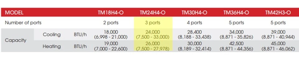
It’s important to note that not all approved combinations follow this exact pattern. Many TOSOT configurations genuinely represent more indoor capacity than outdoor capacity. In these cases, if all indoor units demand full capacity simultaneously, the system operates within the constraints of the outdoor unit’s maximum capacity, potentially resulting in slight derating of indoor units.
This characteristic exemplifies the versatility of inverter compressor technology as a modulating system. My example of three 9K indoor units with the TM24H4-O outdoor unit demonstrates how this can benefit both contractors and customers. Instead of upsizing to the more expensive TM30H4-O outdoor unit, you can maintain necessary capacity for all weather conditions while keeping equipment costs lower ultimately helping you get the job!
Leveraging advanced tech like inverter systems sets you apart. Property.com helps you capitalize on that edge. Gain exclusive access in your region, impress homeowners with ‘[Know Before You Go](https://mccreadie.property.com)’ insights (like potential energy savings!), and close more deals with flexible financing options. Secure your premium spot and early adopter pricing today.
This principle applies not only to the Standard Multi-Zone units in my example but extends to the UltraHeat Multi-Zone series as well:
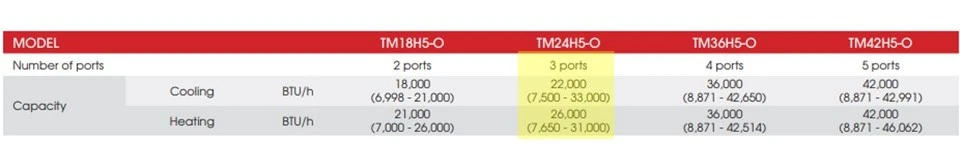
## Final Thoughts: Redefining HVAC Possibilities
Even after years of working with TOSOT products, I continue to discover technical capabilities that challenge conventional HVAC assumptions and provide practical advantages for installations. These revelations continually reignite my enthusiasm for the technology.
The inverter compressor truly represents the greatest invention in the HVAC industry in my lifetime. Its ability to modulate performance, adapt to varying loads, and provide flexible installation options makes previously unthinkable system configurations not just possible but practical and efficient.
For HVAC professionals looking to provide cost-effective solutions without compromising performance, understanding these capacity relationships in inverter-driven systems provides a competitive edge that benefits both contractors and customers alike.
document.addEventListener('DOMContentLoaded', function() {
var links = document.querySelectorAll('a[href="https://mccreadie.property.com"]');
links.forEach(function(link) {
link.addEventListener('click', function(event) {
if (typeof gtag === 'function') {
gtag('event', 'click', {
'event\_category': 'Outbound Link',
'event\_label': window.location.pathname,
'transport\_type': 'beacon'
});
}
});
});
});
{
"@context": "https://schema.org",
"@type": "TechArticle",
"headline": "Inverter Compressor Technology: How TOSOT Mini Splits Maximize Indoor Capacity",
"description": "Discover how inverter compressor technology in TOSOT multi-zone mini splits allows for greater indoor capacity than outdoor capacity, providing flexibility and cost-efficiency for HVAC professionals.",
"author": {
"@type": "Person",
"name": "HVAC Know It All"
},
"publisher": {
"@type": "Organization",
"name": "HVAC Know It All",
"logo": {
"@type": "ImageObject",
"url": "https://hvacknowitall.com/wp-content/uploads/2022/09/hva-know-it-all-logo.png"
}
},
"image": "https://hvacknowitall.com/wp-content/uploads/2023/02/AC-Ductless-Capacity-Charts-1.webp",
"mainEntityOfPage": {
"@type": "WebPage",
"@id": "https://hvacknowitall.com/the-inverter-compressor/"
},
"mentions": [
{
"@type": "Product",
"name": "TOSOT Standard Multi-Zone Mini Split",
"manufacturer": {
"@type": "Organization",
"name": "TOSOT"
}
},
{
"@type": "Product",
"name": "TOSOT UltraHeat Multi-Zone",
"manufacturer": {
"@type": "Organization",
"name": "TOSOT"
}
}
],
"articleSection": "HVAC Technology",
"keywords": "inverter compressor, TOSOT mini split, multi zone mini split, HVAC capacity, ductless systems"
}
--------------------------------------------------
# ID: 234
## Title: Thermal Imaging for HVAC: Essential Applications for Modern Technicians
## Type: blog_post
## Author: Gary McCreadie
## Publish Date: 2022-03-05T16:47:00
## Word Count: 1277
## Categories: Education
## Tags: None
## Permalink: https://hvacknowitall.com/blog/thermal-imaging-for-hvac
## Description:
# Thermal Imaging for HVAC: Essential Applications for Modern Technicians
Thermal imaging has revolutionized how HVAC professionals diagnose problems and verify system performance. Once considered a luxury tool reserved for specialized technicians, thermal cameras have now become accessible to the average HVAC professional thanks to significant price reductions in recent years.
Today’s affordable thermal cameras offer powerful diagnostic capabilities that help identify issues invisible to the naked eye, demonstrate system performance to customers, and verify proper operation across various applications.
This article explores practical uses for thermal cameras in everyday HVAC work, showing how this technology can enhance your troubleshooting capabilities and service quality.
The following video demonstrates additional applications for thermal cameras in HVAC using the [HIKMICRO](https://www.hikmicrotech.com/en/product-c-detail/15) B20:
Loose electrical connections create resistance, which generates heat and increases amperage draw. This excess heat can lead to several significant problems:
- Premature component failure due to prolonged overheating
- Burned wiring insulation that creates fire hazards
- Emergency service calls that could have been prevented
- Shortened equipment lifespan
Before thermal imaging became accessible, technicians had to manually check each connection pointa time-consuming process that often meant disconnecting power multiple times during inspection.
Thermal cameras have transformed this process entirely. Now, technicians can:
1. Perform a quick scan of an energized electrical panel
2. Instantly identify hot spots that indicate loose connections or overloaded circuits
3. Power down only after locating specific problem areas
4. Make targeted repairs to the affected connections
This approach dramatically reduces diagnostic time while improving accuracy. In the past, only specialized electrical contractors with expensive equipment could provide this service. Today, any HVAC technician with a moderately priced thermal camera can perform these inspections during routine maintenance visits.

Thermal cameras excel at identifying energy waste through air leakage detection, particularly when combined with blower door testing.
### How Blower Door Testing Works with Thermal Imaging
Blower door tests create pressure differences between indoor and outdoor environments to reveal air leakage points in the building envelope. When combined with thermal imaging, this technique becomes even more powerful:
1. The blower door fan depressurizes the building, creating negative pressure inside
2. This negative pressure actively pulls outside air through any leaks in the envelope
3. When temperature differences exist between indoor and outdoor air, thermal cameras can visualize these intrusions
For effective thermal detection, you need a sufficient temperature differential (delta T) between indoor and outdoor airideally 15F or greater. For example:
- Indoor temperature: 70F
- Outdoor temperature: 50F
- Delta T: 20F (sufficient for detection)
With these conditions and the building under negative pressure, a thermal camera will clearly show cooler outdoor air infiltrating through compromised windows, door frames, electrical outlets, and other leak points. This visual evidence helps technicians pinpoint exactly where energy-saving improvements are needed.
Just like a thermal camera reveals hidden issues, Property.com uncovers critical homeowner insights before you even arrive. Access permit history, home value, potential savings, and more with our ‘[Know Before You Go](https://mccreadie.property.com)’ tool. Join our exclusive network of certified pros, boost your SEO with a custom subdomain, and manage your reputation effortlessly. Limited spots available per region secure your advantage today. Learn more about Property.com’s premium tools for top HVAC contractors.
Thermal cameras don’t directly “see” air movement, but they can visualize temperature differences that reveal air distribution patterns when conditions are right.
This capability is particularly valuable in commercial spaces where verifying consistent air distribution is crucial for comfort and efficiency. With a properly set up thermal scan, you can:
- Confirm which diffusers and grills are actively supplying conditioned air
- Visualize the “throw” pattern (the distance air travels from the supply outlet)
- Identify areas receiving inadequate air distribution
- Detect unexpected temperature stratification in the space
For best results when visualizing air patterns:
1. Create a significant temperature differential between supply air and room air
2. Capture thermal images shortly after system startup when temperature differences are greatest
3. Take comparative images of different supply outlets under similar conditions
Remember that as supply air mixes with room air, the temperature differential diminishes, making patterns less visible over time. This makes timing important when conducting these evaluations.
This technique provides valuable reference points when balancing systems or troubleshooting comfort complaints in larger commercial installations.
Many HVAC technicians underutilize their thermal cameras by not properly adjusting the emissivity settings for different materials. This single setting can dramatically affect reading accuracy.
### What Is Emissivity?
Emissivity refers to how effectively a surface emits thermal energy compared to a perfect emitter (known as a “blackbody”). It’s expressed as a value between 0 and 1:
- **High emissivity (0.90-0.99)**: Materials that efficiently emit thermal energy, such as non-shiny surfaces, rubber, painted surfaces
- **Low emissivity (0.01-0.60)**: Materials that reflect more thermal energy than they emit, such as polished metals and reflective surfaces
As Brent Lammert from Hikmicro explains: “Thermal energy can be emitted by a target or reflected by it. Emissivity represents the percentage of what thermal energy is reflected versus emitted. The more reflective the surface, the lower the emissivity value it will have.”
Listen to Brent Lammert discuss thermal imaging with me on the HVAC Know It All Podcast.
### Setting Emissivity Correctly
Most thermal cameras offer:
1. **Pre-programmed settings** for common materials (recommended for beginners)
2. **Custom settings** for precise applications (recommended for experienced users)
For custom settings, consult an emissivity table for the specific material you’re measuring before adjusting your camera.
### Pro Tip for Comparing Different Materials
When comparing two surfaces with different textures (and therefore different emissivity values), your readings may be inconsistent. Here’s a professional workaround:
1. Apply a small piece of electrical tape to each surface you want to compare
2. Set your camera’s emissivity to 0.95-0.97 (the emissivity of electrical tape)
3. Measure the temperature of the tape on each surface
This technique creates a consistent measurement baseline, allowing for accurate temperature comparisons between materials that would otherwise be difficult to measure directly.
## Conclusion
Thermal imaging has transformed from a specialized luxury to an essential diagnostic tool for modern HVAC professionals. The applications we’ve coveredelectrical troubleshooting, energy assessments, airflow visualization, and proper emissivity settingsrepresent just a few ways this technology can improve your service efficiency and quality.
To get the most from your thermal camera:
- Read the manufacturer’s documentation thoroughly
- Practice in controlled environments to understand its capabilities and limitations
- Experiment with different settings for various materials and applications
- Use thermal imaging as part of your regular diagnostic process, not just for special cases
As you integrate thermal imaging into your daily workflow, you’ll discover countless applications that save time, improve accuracy, and provide compelling visual evidence to help customers understand system issues.
Boost your HVAC skills and stay ahead of the competition by exploring our comprehensive [blog articles](https://hvacknowitall.com/blog), tuning in to our technician-focused [podcast](https://hvacknowitall.com/podcasts), and subscribing to our YouTube channel for exclusive tips and best practices in HVACR.
document.addEventListener('DOMContentLoaded', function() {
var links = document.querySelectorAll('a[href="https://mccreadie.property.com"]');
links.forEach(function(link) {
link.addEventListener('click', function(event) {
if (typeof gtag === 'function') {
gtag('event', 'click', {
'event\_category': 'Outbound Link',
'event\_label': window.location.pathname,
'transport\_type': 'beacon'
});
}
});
});
});
{
"@context": "https://schema.org",
"@type": "TechArticle",
"headline": "Thermal Imaging for HVAC: Essential Applications for Modern Technicians",
"description": "Discover how affordable thermal cameras are transforming HVAC diagnostics. Learn practical applications for electrical troubleshooting, energy management, and airflow analysis.",
"keywords": "HVAC, thermal imaging, thermal camera, HIKMICRO, emissivity, electrical troubleshooting, energy management, airflow patterns",
"author": {
"@type": "Person",
"name": "HVAC Know It All"
},
"publisher": {
"@type": "Organization",
"name": "HVAC Know It All",
"logo": {
"@type": "ImageObject",
"url": "https://hvacknowitall.com/wp-content/uploads/2022/03/hvackia-logo-horiz.png"
}
},
"image": "https://hvacknowitall.com/wp-content/uploads/2022/03/blower-door-testing.webp",
"mainEntityOfPage": {
"@type": "WebPage",
"@id": "https://hvacknowitall.com/blog/thermal-imaging-for-hvac"
}
}
--------------------------------------------------
# ID: 204
## Title: The Magic of Refrigerant: How Air-to-Air Heat Pumps Extract Heat from Cold Air
## Type: blog_post
## Author: Gerry Wagner
## Publish Date: 2022-01-16T16:05:00
## Word Count: 1314
## Categories: Refrigerants
## Tags: None
## Permalink: https://hvacknowitall.com/blog/how-refrigerant-works
## Description:
## **THE MAGIC OF REFRIGERANT**
Mankind discovered fire approximately two million years ago. While I’m experienced in HVAC, I’m not quite that old, so I’ll trust the scientists on this timeline. Shortly after discovering fire, early humans began using it for one of its most practical applications: generating heat.
Water, being abundant and readily available, became the natural medium for transferring this heat. By heating water with fire and moving the wateror the steam it produced upon boilingto areas requiring warmth, our ancestors created the first rudimentary heating systems.
Hydronic heating systems can be traced back to the late 14th century, while steam heat documentation dates to as early as 1784. Consequently, when most of us think about central heating systems, we envision fire and water as the essential elements.
However, modern [**air-to-air heat pump systems**](https://phyxter.ai/blog/how-does-a-heat-pump-work) challenge this traditional thinking. Many homeowners struggle to understand how a system without fire or water can extract heat from outdoor air at temperatures as low as -30C (-22F). The answer lies in what I consider truly magical: the unique properties of refrigerant.
What many end users don’t realize is that air conditioners don’t create coolingthey extract heat from a room. In a cooling scenario, the **evaporator** (the coil in the conditioned room) passes room air over it via a fan. The **refrigerant** flowing inside the coil absorbs heat from the room air and transports it to the outside unit (**condenser**) where the heat is extracted (again via a fan) and dissipated into the outdoor atmosphere.
Now for the magical part: R410A refrigerant boils at an incredibly low temperature of -48.5C (-55.3F). This remarkable property allows it to absorb heat even when outdoor air temperatures plummet to -30C (-22F).
Making sense now? The transfer medium (refrigerant) used in an air-to-air heat pump is where the “magic” happenswithout it, our heating technology would be significantly less advanced.
Air-to-air heat pumps in HEAT mode simply reverse the [**refrigeration cycle**](https://www.hvacknowitall.com/blogs/blog/595767-the-refrigeration-cycle-explained) described earlier. The outdoor unit coil becomes the evaporator, and the indoor unit coil becomes the condenser, releasing the heat extracted from outdoor air into your home.
It’s also crucial to understand that the refrigerant changes state (from liquid to liquid/vapor to gas) as it circulates throughout the system. This phase change process is fundamental to how heat pumps work.
As we learned in elementary science, matter can change state. What’s less commonly explained is that when matter changes state, it produces energy during that processenergy that an air-to-air heat pump harnesses and converts into heat for your home.
The development of the inverter compressorthe “pump” in the air-to-air heat pumptook this technology to another level entirely.
An **inverter compressor** is best described as a modulating compressor, similar to your car’s engine. While homeowners aren’t expected to understand the technical details of compressor operation, most have a good understanding of how automobiles work.
When you push the gas pedal in your car, it accelerates. When you ease off the gas, it slows down. And when you set the cruise control, the car maintains a consistent speed. This is precisely how an inverter compressor works!
When the heating or cooling demand is high, the compressor will run up to 3600 RPMsimilar to conventional compressors. The critical difference is that when the demand decreases, the inverter compressor “eases off the gas,” using less energy while still providing comfort.
When the room temperature reaches the user’s desired setpoint (whether that’s 68F/20C, 70F/21C, or 72F/22C), the compressor enters “cruise control” mode, using just enough energy to maintain that comfortable temperature consistently.
Explaining complex tech like inverter heat pumps? Enhance your credibility and close more deals with Property.com. Our ‘[Know Before You Go](https://mccreadie.property.com)’ tool provides homeowner insights, while our exclusive network and reputation management tools establish you as the trusted expert. Limited spots available per region. Become a Property.com Pro today.
Modern air-to-air heat pumps offer significant efficiency advantages over traditional heating systems. By moving heat rather than generating it, heat pumps can deliver up to 300% efficiencymeaning for each unit of electricity consumed, they provide three units of heating energy. This translates to lower utility bills and reduced environmental impact.
In moderate climates, homeowners can expect energy savings of 30-40% compared to conventional electric resistance heating. Even in colder regions where temperatures regularly drop below freezing, today’s advanced heat pumps maintain impressive efficiency, though they may require auxiliary heat during extreme cold snaps.
The higher initial investment in heat pump technology typically pays for itself through these operational savings, with payback periods ranging from 3-7 years depending on local energy costs and climate conditions.
As we approach the conclusion, I must highlight the latest advancement in inverter compressor technology that adds another level of energy efficiency and low-temperature heating capability to air-to-air heat pumps.
TOSOT has developed what they call the “two-stage enhanced vapor injection compressor.” Now, being the straightforward instructor many of you know from my TOSOT product training events, I’ll be brutally honest: calling a compressor “vapor injection” is somewhat like saying your beer is “fire-brewed.” Of course it isthat’s what brewing entails!
The Stroh Brewery Company clearly had clever marketing that took an industry-standard practice and made it sound unique. Similarly, ALL compressors involve vapor injectionwe never compress liquid refrigerant, as that would cause severe system damage.
What makes the TOSOT system truly special and innovative is the **“two-stage”** portion of its description.
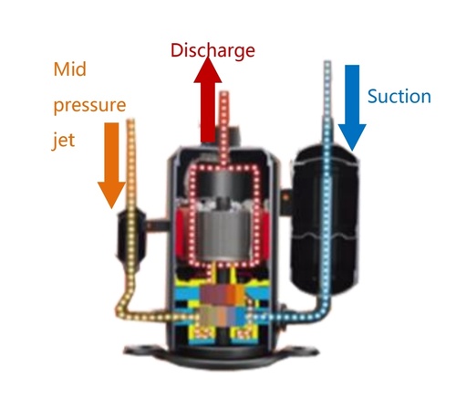
Adding a second “injection” point for refrigerant vapor at two different pressures allows for even greater energy production (in this context, heat). This occurs because energy is produced not only when matter changes state but also when that matter experiences pressure changes. When refrigerant moves between these different pressure zones, it releases additional thermal energy that conventional single-stage systems cannot capture.
## **TRANSLATING TECHNICAL MAGIC TO CUSTOMER VALUE**
HVAC professionals reading this article might be thinking, “Yeah, I knew all this already.” My hope is that this explanation helps you communicate the remarkable attributes of air-to-air heat pumps to your customers in accessible terms.
Technology has advanced tremendously over our long history, and while much of it may seem obvious to professionals, it’s worth taking a moment to appreciate the “magic” that defines our trade. When customers understand the ingenious principles behind heat pump operation, they’re more likely to appreciate the value of investing in this efficient, forward-thinking technology.
The next time a customer asks how a heat pump can possibly extract warmth from freezing air, you’ll have the perfect explanation: it’s not magicit’s refrigerant science, perfected through years of engineering innovation.
document.addEventListener('DOMContentLoaded', function() {
var links = document.querySelectorAll('a[href="https://mccreadie.property.com"]');
links.forEach(function(link) {
link.addEventListener('click', function(event) {
if (typeof gtag === 'function') {
gtag('event', 'click', {
'event\_category': 'Outbound Link',
'event\_label': window.location.pathname,
'transport\_type': 'beacon'
});
}
});
});
});
{
"@context": "https://schema.org",
"@type": "TechArticle",
"headline": "The Magic of Refrigerant: How Air-to-Air Heat Pumps Extract Heat from Cold Air",
"description": "Discover how air-to-air heat pumps use refrigerant properties to extract heat from freezing outdoor temperatures as low as -30C, and how inverter compressor technology enhances efficiency.",
"author": {
"@type": "Person",
"name": "HVAC Know It All Expert"
},
"publisher": {
"@type": "Organization",
"name": "HVAC Know It All",
"logo": {
"@type": "ImageObject",
"url": "https://hvacknowitall.com/wp-content/themes/hvacknowitall/images/logo.png"
}
},
"mainEntityOfPage": {
"@type": "WebPage",
"@id": "https://hvacknowitall.com/blog/refrigerant-heat-transfer-in-air-to-air-heat-pumps"
},
"about": [
{
"@type": "Thing",
"name": "Air-to-air heat pump",
"description": "A heating and cooling system that transfers heat between indoor and outdoor air using refrigerant."
},
{
"@type": "Thing",
"name": "Refrigerant",
"description": "A substance with a low boiling point that absorbs heat when it evaporates and releases heat when it condenses."
},
{
"@type": "Thing",
"name": "Inverter compressor",
"description": "A variable-speed compressor that adjusts its output based on heating or cooling demand."
},
{
"@type": "Thing",
"name": "Two-stage vapor injection",
"description": "An advanced compressor technology that uses two refrigerant injection points at different pressures to improve efficiency."
}
]
}
--------------------------------------------------
# ID: 365
## Title: Understanding Heat Pump Reversing Valves: O vs. B Terminal Designations
## Type: blog_post
## Author: Unknown
## Publish Date: 2022-01-14T06:04:00
## Word Count: 1059
## Categories: Heat Pumps
## Tags: None
## Permalink: https://hvacknowitall.com/blog/reversing-valves-and-their-control-designation
## Description:
## Understanding Heat Pump Reversing Valves: O vs. B Terminal Designations
As Gary mentioned in a recent [podcast](https://anchor.fm/dashboard/episode/e1a45p4), **reversing valves** are critical components in heat pump systems that control refrigerant flow direction based on whether heating or cooling is required. One of the most important yet confusing aspects of heat pump installation and service is understanding the control designation of these valvesspecifically, the difference between **O terminals** and **B terminals**.
Reversing valves have a default position when they are not energized, and this default varies by manufacturer. Most manufacturers design their systems to default to heat mode, meaning the **O terminal** is energized during cooling operation. However, some manufacturers use the opposite configuration, where the **B terminal** is energized during heating operation. This distinction is crucial when installing or replacing thermostats and control boards.
Most heat pump manufacturers default to heat mode (reversing valve de-energized), requiring the O terminal to be energized for cooling operation. However, several manufacturers use the opposite approach, defaulting to cooling mode and energizing the B terminal for heating.
| Manufacturers Using B Terminal | Default State |
| --- | --- |
| Rheem | Cooling |
| Ruud | Cooling |
| Weathermaker | Cooling |
| Ameristar | Cooling |
| Bosch Air Source | Cooling |
| (Note: Bosch WSHP uses O) | |
The choice between O and B terminal configurations often stems from historical design decisions and perceived advantages in specific climate zones. In colder regions, defaulting to heat mode (O terminal) provides a fail-safe, ensuring heating capability if valve control is lost, while in warmer climates, some manufacturers prefer defaulting to cooling (B terminal).
Another important consideration with heat pumps involves light commercial systems. While many manufacturers maintain traditional heat pump control wiring for their commercial units, somenotably **Carrier** and **York** use conventional wiring similar to what you’d find in gas furnace with AC installations.
These systems, regardless of cooling stages, use W1 to energize all compressors for heating and W2 to energize auxiliary heat. This differs from standard residential configurations for an important reason: on a call for Y1, the control signal passes through the [economizer](https://svach.lbl.gov/what-is-an-economizer/) control first (in an RTU application) before potentially energizing the stage one compressor contactor.

W1 is used to activate all compressors for heating for several practical reasons:
1. It bypasses the economizer control, preventing unnecessary outside air from entering the airstream
2. It activates all compressors simultaneously since latent heat removal isn’t a concern in heating mode
3. It allows the logic board to determine the appropriate heat pump reversing valve position
In Carrier systems specifically, these logic boards work in conjunction with either a defrost board in their heat pumps or an ignition control board for their gas furnace RTUs.
Navigating diverse heat pump controls and RTU wiring like Carrier’s? Property.com arms certified Pros with exclusive ‘[Know Before You Go](https://mccreadie.property.com)’ property insights, including permit history and system details, helping you prepare effectively. Stand out with Property.com certification and access a network built for top-tier contractors. Limited spots available per region secure yours.
> Back in the day, I worked on packaged water-cooled heat pumps in ceiling spaces where they used mercury thermostats to control them. These heat pumps failed in heating, so a call for W1 would run the heat pump in heating mode. To run in the cooling mode, they took an interesting approach. A call for Y1 would energize the reversing valve, and a call for Y2 would pull in the contactor for the compressor. The building had many heat pumps throughout many floors that were wired this way.
>
> Gary McCreadie
Reversing valve problems are among the most common issues with heat pump systems. Here are key indicators and troubleshooting steps for reversing valve failures:
1. **System blows warm air in cooling mode or cold air in heating mode**: This is the most obvious symptom of a reversing valve malfunction. The valve may be stuck or the solenoid may have failed.
2. **Diagnosis steps**:
3. Check voltage at the reversing valve solenoid (should match the system’s control voltage, typically 24V)
4. Listen for the distinctive “click” when the valve should be changing positions
5. Monitor temperature drops across indoor and outdoor coils to confirm proper refrigerant flow direction
6. Check for mechanical binding by manually actuating the valve (with system power off)
7. **Common failures**:
8. Electrical solenoid failure
9. Internal valve leakage
10. Mechanical binding or sticking
11. Control board or thermostat issues (incorrect configuration for O/B terminal)
When replacing a reversing valve or setting up a new thermostat, always verify the manufacturer’s specific O/B terminal designation to ensure proper operation in both heating and cooling modes.
As with any HVAC system, the most important thing that any technician can do is to **RTFM: Read The Fantastic Manual**. This ensures that the system you’re working on is wired and set up properly at the thermostat, particularly when it comes to correctly configuring reversing valve control designations.
## Stay Updated with HVAC Know It All
The [HVAC Know It All Podcast](https://hvacknowitall.com/podcasts) is your essential resource for staying current with industry developments, technical insights, and professional best practices. Our experienced professionals share knowledge that will sharpen your skills and give you a competitive edge in understanding complex systems like heat pump controls and reversing valve configurations.
document.addEventListener('DOMContentLoaded', function() {
var links = document.querySelectorAll('a[href="https://mccreadie.property.com"]');
links.forEach(function(link) {
link.addEventListener('click', function(event) {
if (typeof gtag === 'function') {
gtag('event', 'click', {
'event\_category': 'Outbound Link',
'event\_label': window.location.pathname,
'transport\_type': 'beacon'
});
}
});
});
});
{
"@context": "https://schema.org",
"@type": "TechArticle",
"headline": "Understanding Heat Pump Reversing Valves: O vs. B Terminal Designations",
"description": "Learn the crucial differences between O and B terminal designations for heat pump reversing valves, manufacturer defaults, and wiring considerations for residential and commercial systems.",
"author": {
"@type": "Person",
"name": "HVAC Know It All"
},
"publisher": {
"@type": "Organization",
"name": "HVAC Know It All",
"logo": {
"@type": "ImageObject",
"url": "https://hvacknowitall.com/wp-content/uploads/logo.png"
}
},
"image": "https://hvacknowitall.com/wp-content/uploads/2022/01/heat-pump-control-board-765x1024.webp",
"mainEntityOfPage": {
"@type": "WebPage",
"@id": "https://hvacknowitall.com/heat-pump-reversing-valves"
},
"articleSection": "HVAC",
"keywords": "heat pump, reversing valve, O terminal, B terminal, HVAC"
}
--------------------------------------------------
# ID: 368
## Title: Internal HVAC Sealants: When and How to Use Them Effectively
## Type: blog_post
## Author: Gary McCreadie
## Publish Date: 2021-11-29T06:09:00
## Word Count: 1553
## Categories: Sealants
## Tags: None
## Permalink: https://hvacknowitall.com/blog/internal-hvac-sealants
## Description:
## Why I Use Internal HVAC Sealants
I have a confession to make. Yes, I use internal HVAC sealants in certain situationsand I’m going to explain exactly when and why.
Internal sealants in the HVAC/R industry have earned a questionable reputation, often for good reason. The older polymer-based formulations would react with moisture and air, sometimes causing system blockages and additional problems down the line.
Unfortunately, some technicians still add sealant cans without proper diagnosis, skipping essential [system leak checks](https://hvacknowitall.com/blog/refrigerant-leak-checking-procedure). This practice continues today, but with the right education and approach, internal sealants can be a valuable tool in specific circumstances.
Service call on a frozen coil
Before considering a leak sealant product, a proper diagnostic process is essential:
1. **Confirm the leak exists** – Is the system actually low on refrigerant?
2. **Locate the leak precisely** – Where exactly is refrigerant escaping?
3. **Evaluate repair options** – Can it be repaired cost-effectively using traditional methods?
When a technician discovers a system short of refrigerant, simply adding leak sealant and leaving is never acceptable. Professional diagnosis requires a methodical approach:
First, perform a thorough leak inspection using an electronic leak detector, followed by soap solution to verify the leak’s presence and severity. Modern electronic detectors can identify extremely small leakssometimes too small to produce visible bubbles with soap testing.
In certain situations, especially with complex evaporator coils, refrigerant dye can be particularly effective. This method excels with thicker evaporator coils containing 5 or more rows where direct visual inspection is challenging.

Once you’ve located the leak, determine if conventional repair methods are feasible. This might include brazing the leak point or cutting and re-flaring a damaged flare joint.
However, when you discover a leak in a porous evaporator, you’re likely dealing with formicary corrosion that has weakened the copper. Attempting to cut into such a fragile coil can create additional leak points, especially if the coil has deteriorated significantly.
In these cases, complete coil replacement typically offers the most reliable repair option. Attempting extensive repairs on an aged, corroded coil often proves costly and ineffective for the customer, potentially causing more harm than good.
Sometimes, though, circumstances demand immediate solutionsperhaps the system is critical for operations, replacement parts aren’t readily available, or the customer needs functionality restored immediately.
This is precisely when a properly trained technician, knowledgeable about various repair options, might consider an internal sealant as part of the solution.
Remember, sealant installation should always be presented as a customer option, explored only in appropriate scenarios as a means of restoring system operation.
**Facing tough repair decisions on older HVAC systems?** Property.com offers exclusive tools for top-tier contractors. Access our ‘[Know Before You Go](https://mccreadie.property.com)’ feature for homeowner insights like permit history and home value, helping you assess repair viability and present solutions effectively. Plus, gain enhanced credibility with a Property.com subdomain and connect with our network. Limited spots available per region. **Learn more about joining Property.com’s exclusive network.**
Sealant technology has evolved significantly over the years. Here’s what distinguishes modern oil-based formulas from older polymer-based options:
| Feature | Polymer-Based Sealants | Oil-Based Sealants (like AC Smart Seal) |
| --- | --- | --- |
| Reaction | Reacts with moisture/air | Non-reactive, inert |
| Risk of blockage | Higher potential | Minimal risk when properly applied |
| Application range | Limited | Works in various system types |
| Long-term effects | Can harden/solidify | Maintains elasticity |
I’ll be transparent about my experience: since December 2017, I’ve used [AC Smart Seal](https://www.coolairproducts.net/products/ac-smartseal/) in 10-15 different applications, from walk-in refrigeration to reach-in coolers and even a Liebert unit in a small data center.
I can report that none of these systems has experienced a failed compressor or blocked metering device. The key reason lies in the product’s oil-based formula rather than polymer composition.
According to the manufacturer, AC Smart Seal doesn’t react with air or moistureit remains inert and non-reactive within the system. The sealing action works mechanically: as refrigerant attempts to escape through a leak point, the oil-based sealant is carried along with it. The elastic molecules then begin to aggregate at the leak site, gradually building up until they create an effective seal.
**Important limitation:** Does it work in every situation? Absolutely not.
The leak must be small enough for the sealant to be effective. If you discover a significant leak on a brazed joint, traditional repair remains the proper approach. However, for seasonal mystery leaks or when dealing with a corroded evaporator coil, an internal leak sealant might be appropriate.
Using a quality sealant provides operational runway until a more permanent repair can be scheduled, depending on the system’s criticality and application.
Listen to an old-school episode of the HVAC Know It All Podcast discussing internal sealants
While internal sealants can be effective in certain situations, they are not universal solutions. Avoid using sealants in these scenarios:
1. **Large, visible leaks** – Sealants are designed for micro-leaks, not significant refrigerant loss points
2. **New or in-warranty equipment** – Using sealants could void manufacturer warranties
3. **Systems with existing restrictions** – If the system already shows signs of restricted flow
4. **Before proper diagnosis** – Never use sealants as a “quick fix” without identifying the leak source
5. **High-precision applications** – Critical systems requiring precise performance specifications
6. **When proper repairs are readily achievable** – If the leak is accessible and easily repairable through conventional methods
Remember that sealants are meant to be part of your technical arsenalnot a replacement for proper repair techniques when those are feasible and cost-effective.
Early in 2021, I encountered a frozen evaporator coil on a Liebert unit.
After allowing it to thaw completely, I determined the system was operating with an insufficient refrigerant chargea clear indication of a leak. The system had refrigerant dye added years earlier, and my electronic leak detector was registering activity around the evaporator coil.
Given the coil’s size and the leak’s location, soap testing wasn’t practical for precise leak identification. Using a UV blacklight, I located a very small leak that wasn’t easily accessible for conventional repair without significant cost and effort.
Considering the unit’s age, I discussed replacement options with the customer. In the meantime, they agreed to try a sealant solution based on my explanation of previous successful applications with [AC Smart Seal](https://hvacknowitall.com/blog/ac-leak-sealant-ac-smart-seal). With an aging system already exhibiting problems, they had little to lose.
Here’s how the repair process unfolded:
First, I confirmed the system was operating with low refrigerant charge:
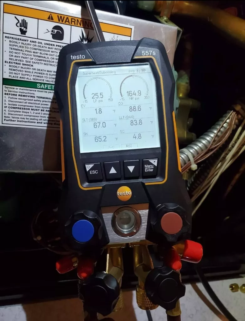
Next, I carefully added AC Smart Seal according to manufacturer specifications:
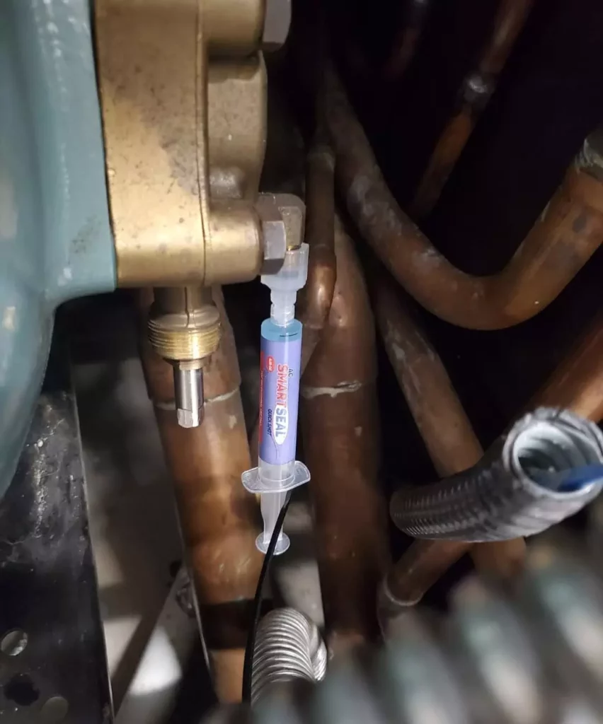
After adding the sealant, I properly charged the system using superheat and subcooling methods as my precise guides:
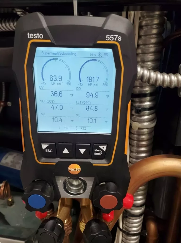
Several months later, I returned to check the system and found it functioning with a full, stable charge. My leak detector no longer registered any refrigerant emissions in the area that had previously shown leakage.
I recently visited the site again before writing this article, and the system continues to maintain its proper charge leveldemonstrating the long-term effectiveness of the solution in this particular application.
## In Conclusion: A Practical Approach to Internal Sealants
The purist approach to HVAC repairs might reject internal sealants categorically, but my systematic testing over four years across diverse applications reveals a more nuanced reality: when properly applied in appropriate situations, quality oil-based sealants can provide effective solutions without system failures.
The key elements for success include:
1. **Thorough verification** of the leak’s existence and precise location
2. **Proper evaluation** of traditional repair options first
3. **Careful selection** of appropriate cases (small, otherwise difficult-to-repair leaks)
4. **Using quality products** designed for HVAC/R applications
5. **Setting appropriate expectations** with customers about the solution’s nature
Internal sealants aren’t magical cure-alls or replacements for proper repair techniques, but they do deserve consideration as part of a professional technician’s problem-solving toolkit when circumstances warrant their use.
When conventional repairs would require excessive labor, when replacement parts aren’t immediately available, or when critical systems need temporary restoration until permanent solutions can be implemented, a carefully selected internal sealant might be the most practical approach to serve your customer’s immediate needs.
document.addEventListener('DOMContentLoaded', function() {
var links = document.querySelectorAll('a[href="https://mccreadie.property.com"]');
links.forEach(function(link) {
link.addEventListener('click', function(event) {
if (typeof gtag === 'function') {
gtag('event', 'click', {
'event\_category': 'Outbound Link',
'event\_label': window.location.pathname,
'transport\_type': 'beacon'
});
}
});
});
});
{
"@context": "https://schema.org",
"@type": "TechArticle",
"headline": "Internal HVAC Sealants: When and How to Use Them Effectively",
"description": "Learn when internal HVAC sealants are appropriate, how to properly diagnose refrigerant leaks, and the advantages of oil-based formulas like AC Smart Seal from an experienced technician's perspective.",
"author": {
"@type": "Person",
"name": "HVAC Know It All"
},
"publisher": {
"@type": "Organization",
"name": "HVAC Know It All",
"logo": {
"@type": "ImageObject",
"url": "https://hvacknowitall.com/wp-content/uploads/2021/02/HVAC-Know-It-All-Logo-300x300.jpg"
}
},
"image": "https://hvacknowitall.com/wp-content/uploads/2022/10/Electronic-Refrigerant-Leak-Detector-1024x683.webp",
"mainEntity": {
"@type": "Thing",
"name": "HVAC Internal Sealant",
"description": "A solution used to seal small refrigerant leaks in HVAC systems from inside the refrigerant circuit."
},
"mentions": [
{
"@type": "Product",
"name": "AC Smart Seal",
"manufacturer": {
"@type": "Organization",
"name": "Cool Air Products"
},
"url": "https://www.coolairproducts.net/products/ac-smartseal/"
},
{
"@type": "Thing",
"name": "Evaporator Coil Leak",
"description": "A common HVAC issue where refrigerant escapes from small holes in the evaporator coil."
}
]
}
--------------------------------------------------
# ID: 172
## Title: The Evolution of Mini-Split Air Conditioners: From Comfort-Aire to Modern HVAC Technology
## Type: blog_post
## Author: Gerry Wagner
## Publish Date: 2021-11-27T15:24:00
## Word Count: 1280
## Categories: Air Conditioning
## Tags: None
## Permalink: https://hvacknowitall.com/blog/history-of-the-mini-split-air-conditioner
## Description:
# The Evolution of Mini-Split Air Conditioners: From Comfort-Aire to Modern HVAC Technology
## The Origins: Discovering Mini-Split History
Prior to my time at Bathica TOSOT, I did some contract work for Heat Controller, Inc. out of Jackson, MI. You know them by the brand name Comfort-Aire.
I had the privilege of learning the true history of mini-split air conditioning systems directly from someone who witnessed its development firsthandMr. Don Peck, who served as CEO of Heat Controller and dedicated over 50 years of his career to the company.
This insider perspective reveals how mini-split technology evolved from its earliest prototype to today’s high-efficiency systems, demonstrating just how far HVAC innovation has progressed over five decades.
Don was always proud to tell me that the FIRST mini split was developed by Heat Controller. In his exact words:
“The first introduction in 1965 was the Comfort-Aire Twin which was a window air conditioner with a split cabinet design that allowed the window to close into the center of the unit with the compressor and the condenser fan on the outside of the window and the indoor fan on the inside making for a very quiet application”.

This innovative approach solved a significant problem with traditional window units: noise. By positioning the compressor and condenser components outside while keeping only the quiet indoor fan inside, the Twin offered dramatically improved comfort for users.
Building on the Twin’s success, Heat Controller developed what would become recognized as the first true mini-split air conditioner. The Twin Pac was initially created for Sears in 1969 and marketed as the “Sears Modular Central Air Conditioning System.”
The original Twin Pac lineup included two models:
– A 6,000 BTU unit operating on 115V power
– A 16,000 BTU unit requiring 230V power
These pioneering systems came with just 8 feet of refrigerant lines, featured quick-connect fittings, and included a double wrench kit for making the connectionsimplifying installation for contractors and technicians.
By 1971, the Twin Pac became available under Heat Controller’s own Comfort-Aire brand. The product line expanded to three capacity options:
– 6,000 BTU
– 11,000 BTU
– 16,000 BTU
Perhaps more importantly, the refrigerant line accessories were upgraded to allow installations with up to 19 feet between indoor and outdoor unitsnearly tripling the installation flexibility of the original design.
WW Grainger and Harry Alter Co. quickly became the largest wholesale distributors for the innovative system. Unfortunately, the Twin Pac ultimately disappeared from the market in the late 1980s when the federal government implemented the first minimum efficiency standard requiring an EER of 8.0. The Twin Pac was classified as a split system rather than a room unit, which subjected it to different regulatory requirements.
**Here is an actual piece of marketing literature for the Comfort-Aire Twin Pac:**
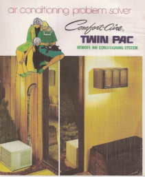
Look at the indoor unitseems like EVERYTHING was wood grain back in the 70’s!
Don always made a point to say that in 1974, the Comfort-Aire Twin Pac won the Product of the Year award in the state of Michiganit beat out the 1974 Ford Mustang.
Now, you might say that just about anything should have beaten this car

But those of us who lived through that era know Ford sold these vehicles by the thousands. For any non-automotive product to win such recognition in Michigan was virtually unprecedented at the time!
Now, let’s hop into our metaphorical 1982 DeLorean DMC-12, set the flux capacitor to 2021, and travel 52 years forward from the introduction of the first mini-split system in North America.
During these five decades, technology advanced dramatically across all industries:
– Space exploration progressed from the lunar module to the space shuttle to SpaceX rockets
– Automotive engineering evolved from the gas-guzzling 1969 Ford Mustang with its 390 cu.in. (6.4 liter) V8 to the fuel-efficient 1974 Mustang II with a 2.3-liter 4-cylinder, and finally to the 2021 Mustang Shelby GT500 with its supercharged 5.2-liter V8 producing a staggering 760 horsepower
And in the HVAC world, we went from the groundbreaking but limited Comfort-Aire Twin Pac of 1969 with an EER below 8 to modern marvels like the TOSOT LOMOPLUS.
Here we have the TOSOT LOMOPLUS high wall mount unit, representing the pinnacle of current mini-split technology:

A 12K LOMOPLUS IDU is just 39.9” long X 12.1” high X 8.7” deep. Gone is the dated wood grain finish, replaced by a sleek, minimalist aesthetic that blends seamlessly with contemporary interiors.
Let’s compare the specifications to truly appreciate how far mini-split technology has advanced:
- The Comfort-Aire Twin Pac of the early 1980s was discontinued because it couldn’t meet the minimum EER of 8 required at that time.
- By contrast, the 12K LOMOPLUS achieves an impressive EER of 15.3 and a SEER of 30.5, while the 9K LOMOPLUS reaches an even more remarkable EER of 16.5 and SEER of 38.
Installation flexibility has similarly evolved. The original Twin Pac’s maximum lineset length of 19 feet severely limited placement options. The TOSOT LOMOPLUS TW24HQ3D6D, however, can operate with a lineset length of up to 164 feetover eight times the reach of its ancestor!
Just as mini-split technology evolved, so have the tools for top HVAC pros. Property.com offers an exclusive, invitation-only network for certified contractors. Gain a competitive edge with our ‘[Know Before You Go](https://mccreadie.property.com)’ tool, providing homeowner insights like permit history and potential upgrade savings ideal for recommending modern, high-efficiency systems. Boost your credibility with Property.com certification and enhanced SEO. Limited spots per trade/region. Apply for early access and lock in your rate.
## Learn More with HVAC Know It All
The evolution of mini-split technology from the pioneering Comfort-Aire Twin Pac to today’s high-efficiency TOSOT systems demonstrates the remarkable progress in HVAC engineering over five decades. These advancements have revolutionized how we approach comfort cooling, offering quieter operation, dramatically improved energy efficiency, and greater installation flexibility.
Elevate your HVAC expertise and outshine your peers by delving into our informative [blog articles](https://hvacknowitall.com/blog), listening to our [industry-specific podcast](https://hvacknowitall.com/podcasts), and subscribing to our [YouTube channel](https://www.youtube.com/@HVACKnowItAll). We share valuable insights tailored specifically for HVAC technicians seeking to enhance their business and provide exceptional service to their customers.
document.addEventListener('DOMContentLoaded', function() {
var links = document.querySelectorAll('a[href="https://mccreadie.property.com"]');
links.forEach(function(link) {
link.addEventListener('click', function(event) {
if (typeof gtag === 'function') {
gtag('event', 'click', {
'event\_category': 'Outbound Link',
'event\_label': window.location.pathname,
'transport\_type': 'beacon'
});
}
});
});
});
{
"@context": "https://schema.org",
"@type": "Article",
"headline": "The Evolution of Mini-Split Air Conditioners: From Comfort-Aire to Modern HVAC Technology",
"description": "Discover the fascinating history of mini-split air conditioners, from the groundbreaking 1969 Comfort-Aire Twin Pac to today's high-efficiency TOSOT systems. Learn how HVAC technology evolved over five decades.",
"image": "https://hvacknowitall.com/wp-content/uploads/2021/11/TOSOT-LOMOPLUS-high-wall-mount-unit.webp",
"author": {
"@type": "Person",
"name": "HVAC Know It All"
},
"publisher": {
"@type": "Organization",
"name": "HVAC Know It All",
"logo": {
"@type": "ImageObject",
"url": "https://hvacknowitall.com/wp-content/uploads/2021/02/cropped-HvacKnowItAllv2.png"
}
},
"datePublished": "2021-11-01",
"dateModified": "2023-11-01",
"mainEntityOfPage": {
"@type": "WebPage",
"@id": "https://hvacknowitall.com/blog/history-of-the-mini-split-air-conditioner"
},
"about": [
{
"@type": "Thing",
"name": "Mini-Split Air Conditioners",
"description": "A type of ductless HVAC system with separate indoor and outdoor units"
}
],
"mentions": [
{
"@type": "Organization",
"name": "Heat Controller, Inc.",
"location": "Jackson, Michigan",
"brand": "Comfort-Aire"
},
{
"@type": "Person",
"name": "Don Peck",
"jobTitle": "CEO",
"worksFor": "Heat Controller, Inc."
},
{
"@type": "Product",
"name": "Comfort-Aire Twin",
"manufacturer": "Heat Controller, Inc.",
"description": "The first split cabinet design window air conditioner introduced in 1965"
},
{
"@type": "Product",
"name": "Comfort-Aire Twin Pac",
"manufacturer": "Heat Controller, Inc.",
"description": "The first mini-split air conditioner introduced in 1969"
},
{
"@type": "Product",
"name": "TOSOT LOMOPLUS",
"manufacturer": "TOSOT",
"description": "Modern high-efficiency mini-split air conditioner with up to SEER 38 rating"
}
]
}
--------------------------------------------------
# ID: 23
## Title: How To Read HVAC Wiring Diagrams: A Technician’s Guide
## Type: blog_post
## Author: Gary McCreadie
## Publish Date: 2021-11-24T15:18:00
## Word Count: 1326
## Categories: Education, Electrical
## Tags: None
## Permalink: https://hvacknowitall.com/blog/how-to-read-hvac-wiring-diagram
## Description:
## **How To Read HVAC Wiring Diagrams: A Technician’s Guide**
When I first entered the HVAC trade, wiring diagrams looked like a foreign language to me – because they were.
Each equipment manufacturer seemed to have their own way of drawing them out, creating what felt like different dialects or accents of the same technical language. This variation often made interpretation challenging, especially for newcomers.
If you’re currently learning to interpret these crucial diagrams, I understand your frustration. I’ve been exactly where you are, staring at what seemed like an indecipherable maze of lines and symbols.
At their most basic level, wiring diagrams are visual stories that illustrate how electrical components work together in an HVAC system. They show the order of operations for power flow, depict components like fans and compressors, identify power sources, and map the connections between all parts of the system.
These diagrams typically include legends that help you quickly identify components. Mastering the ability to read and understand these diagrams will significantly enhance your [troubleshooting capabilities](https://hvacknowitall.com/blog/general-guide-to-hvac-troubleshooting) and make you a more effective technician.
This is my first ever podcast episode covering basic electrical concepts (please excuse the audio quality as I was just learning the podcast ropes).
Let’s break down the three fundamental components that make up virtually every HVAC wiring diagram:
- Power Supply
- Switches
- Loads
### **Power Supply**
The power supply is the source that energizes the entire circuit. Every load within an HVAC system is designed to operate at specific electrical parameters.
The equipment nameplate always specifies the information required. For example, if a component is rated for 208 VAC, the power supply must match or fall within acceptable limits. Using a power source that’s significantly above or below the nameplate rating can lead to performance issues, component damage, or complete system failure.
**Pro Tip:** A load is a component like a motor or compressor that consumes electrical power to perform work.
In HVAC systems, power supplies typically come from main electrical panels, transformers, or occasionally batteries in control circuits.
### **Switches**
Switches are devices that control the flow of electricity by opening or closing a circuit. They operate through various methods:
- Manual activation
- Automatic response to changing conditions
- Electronic signals from control boards
Every switch has a maximum power rating that should never be exceeded during operation.
An **open switch** breaks the circuit and stops electrical flow. A **closed switch** completes the circuit, allowing electricity to flow through. Experienced technicians often refer to “contacts” when discussing switches, which simply means the conductive parts that touch to complete a circuit or separate to break it.
### **Examples of Switches**
- **High/Low Pressure Switches** – Protect the system from dangerous pressure conditions
- **Relay/Contactor Contacts** – Electrically controlled switches that manage high-current loads
- **Flow Switches** – Detect proper movement of water or air
- **Pressure Switches** – Respond to pressure changes in air or refrigerant systems
For example, in a boiler system, when a pump starts and creates water flow, an inline flow switch detects this movement and changes position from open to closed. This signals the control system that proper flow exists, allowing the boiler to safely operate.
### **Loads**
Loads are the components that actually consume electrical power to perform work. They typically appear at the end of a circuit after power has passed through various switches and safety devices.
Common HVAC loads include:
\* Motors (fan, blower, pump)
\* Compressors
\* Contactor and relay coils
\* Heating elements
\* Indicator lights
Loads draw amperage and convert electrical energy into other forms of energy (mechanical, thermal, etc.).
This simple wiring diagram illustrates all three main components we’ve discussed: power supply, switch, and load. Following this circuit, you can see how electricity flows from the source, through the control switch, and finally to the light bulb (load).
Understanding the standard symbols used in HVAC wiring diagrams is essential for accurate interpretation. While manufacturers may have slight variations, these common symbols remain relatively consistent:
### **Power and Connection Symbols**
- **Lines** – Represent wires connecting components
- **Dotted Lines** – Often indicate control or signal wiring
- **Crossed Lines (without dot)** – Lines passing without connection
- **Crossed Lines (with dot)** – Connected wires
- **Ground Symbol** – Earth/chassis ground connection
- **L1, L2, N** – Line voltage and neutral designations
### **Switch and Control Symbols**
- **Thermostat** – Usually shown as a temperature-dependent switch
- **Pressure Switch** – Depicted with “HP” (high pressure) or “LP” (low pressure)
- **Relay Contacts** – Shown as parallel lines that can connect
- **Manual Switch** – Often a simple break in a line with a toggle indicator
- **Fuse** – Typically shown as a small rectangle or special symbol in a line
### **Load Symbols**
- **Motor** – Circle with an “M” or specific motor designation
- **Compressor** – Circle with a “COMP” label or compressor-specific symbol
- **Heating Element** – Zigzag line
- **Fan** – Circle with fan blade symbol
- **Capacitor** – Traditional capacitor symbol, often with “MFD” rating
### **Manufacturer Variations**
Different HVAC manufacturers often use slightly modified symbols or specialized notations. When working with a specific brand, always refer to their service literature for any unique symbols or notations.
We need to understand not just the components of wiring diagrams but also develop a systematic approach to reading them.
I developed a simple but effective technique during my apprenticeship that I still recommend today:
### **The Finger-Tracing Method**
When facing a new diagram, I would:
1. Remove the access panel to expose the wiring diagram
2. Place my finger at the power source point on the diagram
3. Physically trace the lines, following the path of electricity
4. Pause at each component I encountered
5. Consult the diagram’s legend to understand that component’s function
6. Continue tracing until reaching the end of each circuit
This physical tracing creates a strong mental connection between the abstract diagram and the actual components. When encountering an unfamiliar component, I’d often call technical support for clarification before continuing.
Repeating this process diagram after diagram was definitely my key to success over time. The methodical approach transforms those initially confusing diagrams into clear roadmaps for troubleshooting and repair.
Mastered the diagrams? Now get the homeowner intel you need *before* the call. Property.com’s exclusive ‘[Know Before You Go](https://mccreadie.property.com)’ tool gives certified pros critical insights like permit history and home value. Elevate your service and stand out in your region. Join our invitation-only network for top HVAC professionals. [Learn More at Property.com]
## **Additional Resources for Wiring Diagram Mastery**
Check out this in-depth training video on how to read both wiring and schematic diagrams. It provides visual examples that complement the concepts we’ve covered in this guide. Don’t forget to subscribe to the channel for more technical content.
document.addEventListener('DOMContentLoaded', function() {
var links = document.querySelectorAll('a[href="https://mccreadie.property.com"]');
links.forEach(function(link) {
link.addEventListener('click', function(event) {
if (typeof gtag === 'function') {
gtag('event', 'click', {
'event\_category': 'Outbound Link',
'event\_label': window.location.pathname,
'transport\_type': 'beacon'
});
}
});
});
});
{
"@context": "https://schema.org",
"@type": "HowTo",
"name": "How To Read HVAC Wiring Diagrams: A Technician's Guide",
"description": "Learn how to read and interpret HVAC wiring diagrams, understand power supplies, switches, loads, and common symbols to improve your troubleshooting skills.",
"step": [
{
"@type": "HowToStep",
"name": "Understand Main Components",
"text": "Learn the three fundamental components of HVAC wiring diagrams: power supply, switches, and loads."
},
{
"@type": "HowToStep",
"name": "Identify Common Symbols",
"text": "Familiarize yourself with standard symbols used in HVAC wiring diagrams including power, connection, switch, control, and load symbols."
},
{
"@type": "HowToStep",
"name": "Use the Finger-Tracing Technique",
"text": "Practice tracing the path of electricity from the power source through each component to understand the circuit flow."
}
],
"tool": [
{
"@type": "HowToTool",
"name": "HVAC wiring diagram"
},
{
"@type": "HowToTool",
"name": "Manufacturer's equipment manual"
}
],
"totalTime": "PT30M"
}
--------------------------------------------------
# ID: 209
## Title: Why Do Evaporator Coils Freeze? Common Causes and Solutions
## Type: blog_post
## Author: Gary McCreadie
## Publish Date: 2021-11-21T16:11:00
## Word Count: 1239
## Categories: Air Conditioning, Components
## Tags: None
## Permalink: https://hvacknowitall.com/blog/why-do-evaporators-freeze
## Description:
For a comprehensive understanding of this article, familiarity with the refrigeration cycle is beneficial. If you need a refresher, I recommend reading the **[Refrigeration Cycle Explained](https://hvacknowitall.com/blog/the-refrigeration-cycle-explained)** first.
In HVAC systems, an evaporator coil serves a critical function within the refrigeration cycle it’s where heat absorption occurs from a medium such as air, water, glycol, or brine solution. For air conditioning applications, this article focuses specifically on evaporator coil freezing issues, which indicate system malfunctions requiring diagnosis and correction, unlike refrigeration systems where sub-freezing temperatures are often expected and managed through defrost cycles.
As air passes over an evaporator coil, the coil absorbs heat from the air. For example, air entering at 75F may exit at 55F, creating a 20F temperature differential (delta T). This heat transfer process is fundamental to air conditioning.
It’s important to understand that in refrigeration applications where evaporator temperatures intentionally fall below freezing (32F/0C), systems are designed with defrost cycles. These cycles temporarily halt refrigeration and apply heat via electric elements or redirected hot gas to remove accumulated ice.
You need to remember something very important: regardless of the root cause, frozen evaporator coils always exhibit the same isolated conditionslow pressure and low temperature. While the severity may vary from borderline freezing to significantly below freezing temperatures, the end result remains the sameice formation on the coil.
\*\* Check out this episode of the HVAC Know It All Podcast discussing “Why Evaporators Freeze”\*\*
Let’s examine the primary reasons evaporator coils freeze in air conditioning systems.
When a system has insufficient refrigerant due to leaks or incomplete charging after repairs, the evaporator cannot maintain proper operating pressure. For instance, if a system is designed to operate at a 40F Saturated Suction Temperature (SST), a low charge can cause the evaporator temperature to drop below the freezing point.
While superheat (additional heat beyond the boiling point) may temporarily prevent freezing, the inefficiency caused by low charge leads to longer run times. Combined with dropping return air temperatures during extended operation, this creates ideal conditions for coil freezing.
A properly charged and leak-free system typically prevents freezing under normal operating conditions.
In this Instagram post, I give feedback on a low-charge issue where [AC Smart Seal](https://hvacknowitall.com/blog/ac-leak-sealant-ac-smart-seal) was used on a Liebert unit that had an evaporator micro leak:
> [View this post on Instagram](https://www.instagram.com/p/CTA6BfTnfcs/?utm_source=ig_embed&utm_campaign=loading)
>
> [A post shared by Gary McCreadie HVAC/R Tech/Business Owner (@hvacknowitall1)](https://www.instagram.com/p/CTA6BfTnfcs/?utm_source=ig_embed&utm_campaign=loading)
Airflow restrictions significantly impact evaporator performance and can lead to freezing. Common causes include:
- Clogged air filters
- Dirty evaporator coils
- Blocked secondary heat exchangers in high-efficiency furnaces
- Ductwork restrictions or design issues
- [Failing fan motors](https://hvacknowitall.com/blog/how-hvac-motors-work) or blower assemblies
When airflow decreases, less heat is available for absorption by the refrigerant. This fundamental principle governs evaporator operation: more available heat means higher evaporator pressure and temperature, while less heat results in lower pressure and temperature.
This relationship explains why proper ductwork design, regular filter maintenance, and coil cleaning are critical to preventing freezing issues.
The [SUPCO](https://hvacknowitall.com/sponsor/supco) [Freeze Protection Control](https://www.supco.com/web/supco_live/products/SFPC.html) can be mounted on suction lines up to 7/8” to provide freeze protection:
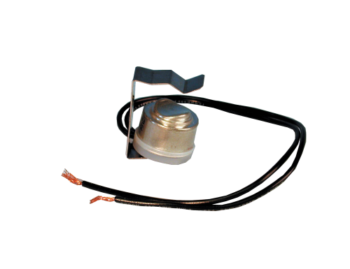
Restrictions in the liquid linetypically in filter driers or metering devicescreate pressure drops that impact evaporator performance. When a filter drier becomes clogged with system debris, the pressure drop means the metering device receives less than a full column of liquid refrigerant.
Similarly, restrictions in metering devices (capillary tubes, fixed orifices, thermal expansion valves, or electronic expansion valves) can create excessive pressure drops. While pressure drops are normal through metering devices, restrictions beyond design parameters will cause abnormally low evaporator pressure and temperature.
\*\* TIP:\*\* A temperature differential of 2F or more measured across a liquid line filter drier indicates partial restriction requiring replacement.
In either scenario, if these pressure/temperature relationships fall below 32F, frost and ice formation begins on the evaporator coil.
In this short video, I cover a quick rundown of a thermal expansion valve. Subscribe to the channel, if you enjoy the content.
When troubleshooting a frozen evaporator, proper diagnosis requires:
1. **Complete defrosting**: Before attempting diagnosis, ensure the evaporator is completely thawed. Diagnosing with ice still present will yield inaccurate readings.
2. **System pressure analysis**: After thawing, check operating pressures against manufacturer specifications.
3. **Temperature measurements**: Verify temperature differentials across components, particularly filter driers and metering devices.
4. **Airflow evaluation**: Measure system airflow and compare to design specifications.
5. **Refrigerant charge verification**: Check superheat and subcooling to confirm proper charge levels.
Each of these diagnostic steps helps identify the underlying cause of freezing, allowing for appropriate corrective action.
Regular maintenance significantly reduces the risk of evaporator freezing:
1. **Quarterly filter replacement**: Prevents airflow restrictions and maintains proper system operation.
2. **Annual professional inspections**: Allows early detection of developing issues before freezing occurs.
3. **Coil cleaning**: Regular cleaning of both evaporator and condenser coils ensures optimal heat transfer.
4. **Refrigerant level checks**: Early detection of small leaks prevents progressive charge loss and freezing.
5. **Airflow verification**: Regular testing ensures proper air distribution and system performance.
6. **Duct inspection**: Identifies and corrects airflow restrictions or design issues.
For homeowners, the most important preventative measure is regular filter replacement and professional maintenance at recommended intervals.
## In Conclusion
All conditions leading to evaporator coil freezing share a common factor: they create abnormally low evaporator pressure and temperature relationships. When these parameters fall below freezing, ice formation occurs regardless of the root cause.
Professional HVAC technicians must accurately diagnose the specific cause of freezingwhether low refrigerant charge, airflow restrictions, or liquid line issuesand implement appropriate corrective measures. Remember that complete thawing of the evaporator is essential before attempting diagnosis to ensure accurate troubleshooting.
Diagnosing tricky issues like frozen evaporators? Property.com Pros leverage exclusive tools like ‘[Know Before You Go](https://mccreadie.property.com)’ for critical homeowner insights *before* the visit. Elevate your service with Property.com certification, boost your SEO with a custom subdomain, and join a limited network of top regional contractors. Secure your early adopter advantage and stand out. Learn more about joining Property.com.
## **Learn More with HVAC Know It All**
Elevate your HVAC expertise and outshine your peers by delving into our informative [blog articles](https://hvacknowitall.com/blog), listening to our [industry-specific podcast](https://hvacknowitall.com/podcasts), and subscribe to our [YouTube channel](https://www.youtube.com/@HVACKnowItAll), where we share valuable insights tailored specifically for HVAC technicians seeking to enhance their business and provide exceptional service.
document.addEventListener('DOMContentLoaded', function() {
var links = document.querySelectorAll('a[href="https://mccreadie.property.com"]');
links.forEach(function(link) {
link.addEventListener('click', function(event) {
if (typeof gtag === 'function') {
gtag('event', 'click', {
'event\_category': 'Outbound Link',
'event\_label': window.location.pathname,
'transport\_type': 'beacon'
});
}
});
});
});
{
"@context": "https://schema.org",
"@type": "TechArticle",
"headline": "Why Do Evaporator Coils Freeze? Common Causes and Solutions",
"description": "Discover why evaporator coils freeze in AC systems, the technical causes behind freezing issues, and professional solutions for diagnosis and prevention.",
"keywords": "evaporator coil freezing, HVAC troubleshooting, air conditioning maintenance, refrigeration cycle, low refrigerant charge, airflow restriction, liquid line restriction",
"articleSection": "HVAC Troubleshooting",
"technical": {
"@type": "TechnicalFeature",
"name": "Evaporator Coil",
"value": "Component in HVAC systems where refrigerant absorbs heat from passing air"
},
"proficiencyLevel": "Intermediate",
"mainEntity": {
"@type": "HowTo",
"name": "Diagnosing Frozen Evaporator Coils",
"step": [
{
"@type": "HowToStep",
"text": "Ensure the evaporator is completely thawed before diagnosis"
},
{
"@type": "HowToStep",
"text": "Check operating pressures against manufacturer specifications"
},
{
"@type": "HowToStep",
"text": "Verify temperature differentials across components"
},
{
"@type": "HowToStep",
"text": "Measure system airflow and compare to design specifications"
},
{
"@type": "HowToStep",
"text": "Check superheat and subcooling to confirm proper charge levels"
}
]
}
}
--------------------------------------------------
# ID: 127
## Title: Domestic Hot Water Generators in Geothermal Systems: Efficiency & Performance Guide
## Type: blog_post
## Author: Matthew Showers
## Publish Date: 2021-11-14T13:39:00
## Word Count: 939
## Categories: Geothermal Systems
## Tags: None
## Permalink: https://hvacknowitall.com/blog/domestic-hot-water-generator
## Description:
As discussed in my previous [article on geothermal heat pump basics](https://www.hvacknowitall.com/blogs/blog/665974-geothermal-heat-pump-basics#.YZEk22DMJPY), geothermal systems offer exceptional efficiency through several innovative features. One particularly valuable component is the Domestic Hot Water Generator (HWG), which harnesses heat from the system’s compressor discharge gas to pre-heat your home’s water supply. This dual-purpose functionality significantly reduces the energy consumption of your water heater while maximizing the overall efficiency of your geothermal investment.
Listen to Matt on the HVAC Know It All Podcast discussing the current state of the industry on this round table episode.
Before the primary refrigerant/water coaxial coil loop, geothermal systems equipped with HWG technology incorporate a secondary heat exchanger specifically for domestic water heating. This heat exchanger contains domestic water that circulates via an internal pump when the HWG function is enabled.
The system works by extracting heat from the compressor’s discharge gasheat that would otherwise be directed entirely to your home’s air or ground loop. This captured heat is transferred to your domestic water supply, which is then pumped into the bottom of your electric water heater or into a separate storage tank if you use a fossil fuel water heater. Rather than heating cold water directly from your main supply, the HWG effectively preheats the water to a setpoint of either 125F or 150F, depending on your configuration settings.
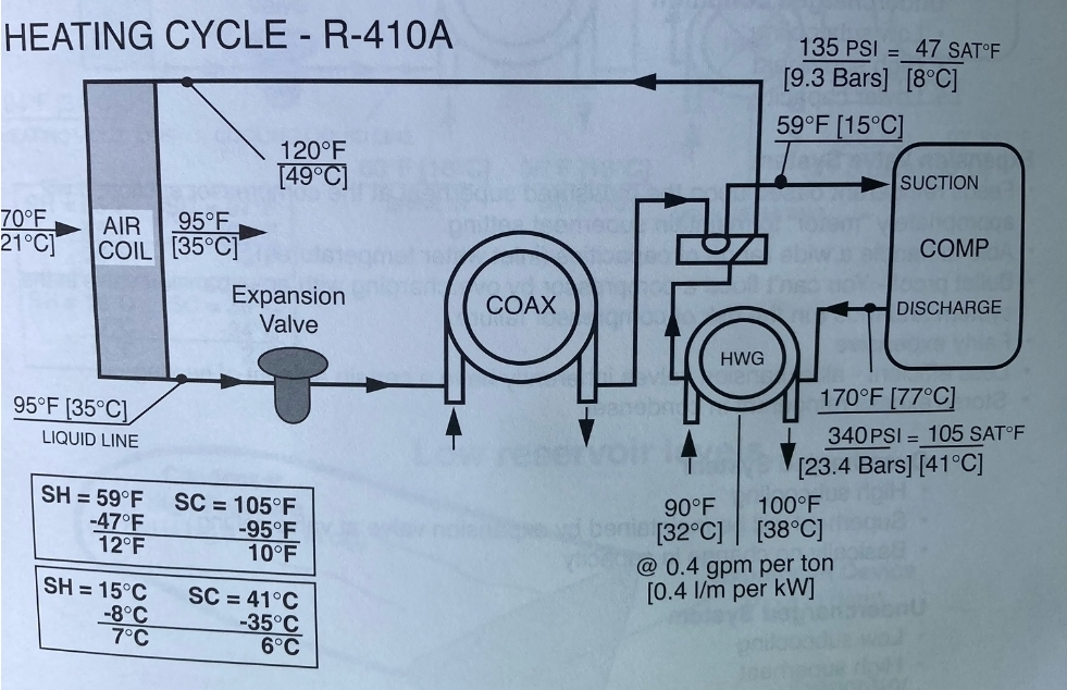*Diagram illustrating the refrigerant flow during heating mode with domestic hot water generation in a geothermal system. Image courtesy of [ClimateMaster](https://www.climatemaster.com/).*
The HWG function does influence overall system performance, which is why manufacturers typically conduct performance testing with the HWG disabled. This impact varies significantly between heating and cooling operation modes:
**During Cooling Mode:**
When your geothermal system runs in cooling mode, it naturally generates heat that must be removed from your home. This heat is typically transferred to the ground loop for rejection. With the HWG enabled, a portion of this heat is diverted to your water supply insteadessentially putting waste heat to productive use without significantly affecting the cooling capacity of your system.
**During Heating Mode:**
The performance impact is more noticeable in heating mode. Since the system is actively generating heat to warm your home, any heat diverted to water heating represents energy not available for space heating. This creates a slight reduction in heating capacity, though the overall energy efficiency of your home may still improve when considering both space and water heating needs together.
Despite this minor performance reduction during heating mode, many professionalsmyself includedrecommend leaving the HWG enabled year-round for maximum overall energy savings. The benefits of reduced water heating costs typically outweigh the slightly reduced heating capacity, especially in moderate climates.
Converting to a geothermal system with an active HWG can significantly reduce your water heating costs compared to conventional water heating methods. The potential savings vary based on several factors:
- **Electric Water Heaters:** Homes with electric water heaters typically see the most dramatic savings, often reducing water heating energy consumption by 30-50% when an HWG is properly implemented.
- **Gas Water Heaters:** While savings are still substantial with gas water heaters, they’re typically lower than with electric units due to the generally lower operating cost of gas. However, HWG pre-heating can still reduce gas water heating costs by 20-40%.
- **Seasonal Considerations:** During cooling season, the HWG essentially provides “free” water heating by utilizing heat that would otherwise be rejected. During heating season, there’s a small trade-off between space heating and water heating efficiency.
The U.S. Department of Energy estimates that water heating accounts for approximately [20% of a typical home’s energy use](https://www.energy.gov/energysaver/water-heating), making the HWG function a significant contributor to a geothermal system’s overall efficiency and cost-effectiveness.
Working on advanced systems like Geothermal? Elevate your service with Property.com. Access exclusive homeowner insights like permit history and potential savings with our ‘[Know Before You Go](https://mccreadie.property.com)’ tool. Secure your limited spot in our network, boost your SEO with a custom subdomain, and gain Property.com Certification. Join the elite network inquire about early adopter benefits today!
## In Conclusion
Domestic Hot Water Generators represent one of the many ways geothermal systems maximize efficiency by providing multiple benefits from a single installation. By capturing and repurposing heat that would otherwise be wasted or directed elsewhere, HWGs can significantly reduce water heating costs while maintaining comfortable indoor temperatures. Despite the minor performance impacts during heating mode, the overall energy efficiency advantages make HWGs a valuable component of any geothermal system.
## **Tune Into the HVAC Know It All Podcast for Expert Tips and Industry Insights**
Ready to dive deeper into HVAC tips and tricks? Tune in to our [**HVAC Know It All podcast**](https://hvacknowitall.com/podcasts), where we discuss the latest industry trends, answer your burning questions, and share expert advice to keep your home comfortable year-round. Don’t miss outsubscribe now and never miss an episode!
document.addEventListener('DOMContentLoaded', function() {
var links = document.querySelectorAll('a[href="https://mccreadie.property.com"]');
links.forEach(function(link) {
link.addEventListener('click', function(event) {
if (typeof gtag === 'function') {
gtag('event', 'click', {
'event\_category': 'Outbound Link',
'event\_label': window.location.pathname,
'transport\_type': 'beacon'
});
}
});
});
});
{
"@context": "https://schema.org",
"@type": "TechArticle",
"headline": "Domestic Hot Water Generators in Geothermal Systems: Efficiency & Performance Guide",
"description": "Learn how Domestic Hot Water Generators (HWG) in geothermal HVAC systems can improve energy efficiency, reduce water heating costs, and impact overall system performance.",
"author": {
"@type": "Person",
"name": "Matt"
},
"publisher": {
"@type": "Organization",
"name": "HVAC Know It All",
"logo": {
"@type": "ImageObject",
"url": "https://hvacknowitall.com/wp-content/uploads/2021/05/HVAC-Know-It-All-Logo.png"
}
},
"image": "https://hvacknowitall.com/wp-content/uploads/2021/11/Heating-Cycle-R410A.webp",
"mainEntityOfPage": {
"@type": "WebPage",
"@id": "https://hvacknowitall.com/blogs/blog/hvac-tip-domestic-hot-water-generator-and-geothermal-systems"
},
"keywords": [
"Domestic Hot Water Generator",
"HWG",
"Geothermal Systems",
"HVAC",
"Energy Efficiency",
"Water Heating"
],
"articleSection": "HVAC Technology",
"proficiencyLevel": "Intermediate"
}
--------------------------------------------------